1
\$\begingroup\$

I want to create an array of multiple electromagnet which I will be controlling using a microcontroller.

I will have around 100 such magnets lined in a squared grid 10x10. Only three or five at a time will be turned on. This array of electromagnets will be responsilbe for driving a smaller natural magnet above it. There will be a small glass sheet sepearting them.

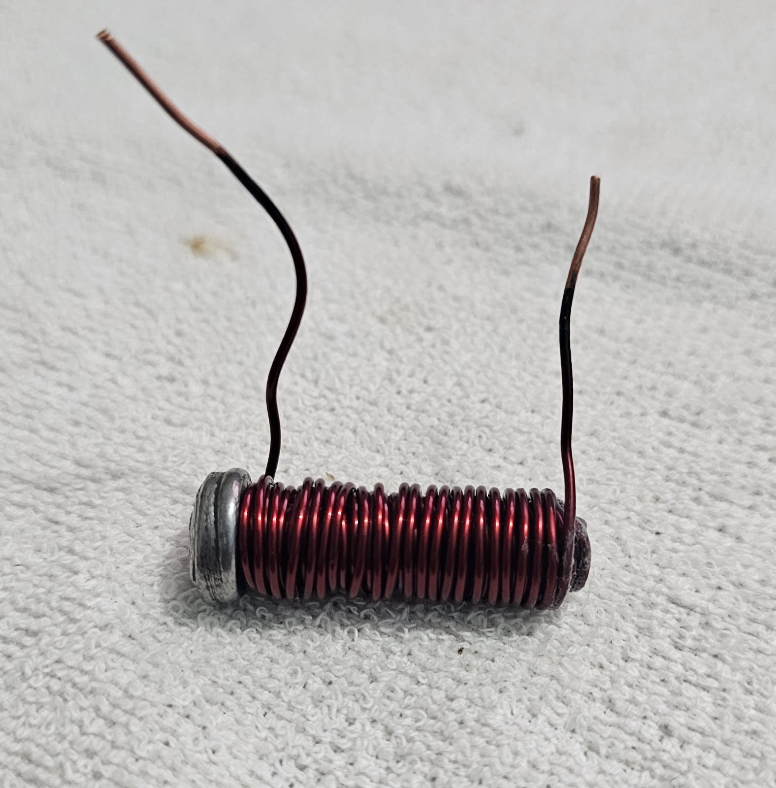
I tried to setup a basic test, creating a very proto-typical model for the desired magnet. As shown in the image below:

enter image description here

Now since it's an 18gauge copper wire, it draws a lot of current which is a good thing for generating powerful magnetic force. But it only works if we hook this contraption with any battery made of electrolytes. As soon as I hook the make-do model of electromagnet with a 12v DC supply, the power-supply does what it supposed to do. That is to protecte itself from the exessive current draw, and its fault prvention circuitry cut the power altogether.

How to make it work? Should I opt for a higher voltage supply, since I have very low resistance because of the short length copper wire and its wide gauge? Should I opt for a higher gauge wire and go with more turns in the coil? Or Should I add some resistors in series to control the excessive current draw?

Here's my dimensions of magnets which I "cannot" change.

  • 5mm core
  • 10mm overall diameter of the electormagnet.
  • 25mm length of the electromagnet.
\$\endgroup\$
1
  • \$\begingroup\$ you can easily answer the question about a resistor experimentally ... higher voltage will push greater current through the coil \$\endgroup\$
    – jsotola
    Commented Nov 29, 2023 at 16:33

2 Answers 2

1
\$\begingroup\$

With your poor magnetic circuit - the iron core only halves the length of air that your H-field has to push flux through - you are going to need all the Ampere.Turns you can get, as it only doubles the field compared to an air core.

To get maximum strength from the magnet, you need to (a) wind as much copper on there as possible and (b) dissipate as much power in it as it will allow. This is independent of voltage, current, turns or wire gauge - they are related as we shall see, but only the mass of copper and the power dissipated actually affect the magnetic field independently.

The maximum power you can use is governed by the maximum temperature it can reach, and the magnet duty cycle. If you want to operate it continuously, then you are limited by its cooling. If you want to apply a single pulse, then you are limited by its heat capacity. Needless to say, most realistic use cases fall between these two simple extremes. It's safest to design for the continuous case. If you can plan for, let's say, a 10% duty cycle, then you can use three times more current than the continuous limit. However, if you operate at 30% or 100% for too long, it will overheat. It's quite easy to operate at 100% if your software crashes - you may want to implement a watchdog to shut the magnet supply down if the software fails.

Once you have decided what power you can use, you change the turns and wire gauge to match your power supply. More turns of thinner wire - higher voltage lower current. Fewer turns of thick wire - lower voltage higher current. But in each case, it's the same total power.

A series resistor will simply increase the voltage needed at the power supply for any given magnet current, so avoid it in the final design. It can be a useful way of limiting the current while you are experimenting though.

To answer your actual questions

Should I opt for a higher voltage supply, since I have very low resistance because of the short length copper wire and its wide gauge?

No, that will only make things worse, you need a lower voltage higher current power supply.

Should I opt for a higher gauge wire and go with more turns in the coil?

That would help with your present supply.

Or Should I add some resistors in series to control the excessive current draw?

To experiment with, yes, but don't design them into the final version.

\$\endgroup\$
4
  • \$\begingroup\$ Could you elaborate on "the iron core only halves the length of air that your H-field has to push flux through" Which lengths of air are we comparing? \$\endgroup\$
    – jonathanjo
    Commented Nov 29, 2023 at 17:19
  • 1
    \$\begingroup\$ @jonathanjo The total length of the magnetic circuit is through the middle of the solenoid, plus back along the outside of the solenoid. The iron bolt divides the middle length of the solenoid by mu, typically thousands, effectively removing it. The outside length remains unaltered. \$\endgroup\$
    – Neil_UK
    Commented Nov 29, 2023 at 17:23
  • \$\begingroup\$ Ah I see! This is the explanation for horseshoe magnets, small air gaps in magnetic tape heads etc? \$\endgroup\$
    – jonathanjo
    Commented Nov 29, 2023 at 17:27
  • 1
    \$\begingroup\$ @jonathanjo ... and the iron return path around relays and motors, and solenoids. \$\endgroup\$
    – Neil_UK
    Commented Nov 29, 2023 at 18:06
1
\$\begingroup\$

This has started somewhere from the middle. You have already nailed how much space you can have per a coil. Ok, but then you should test what number of ampere turns creates the needed force effect to your moving projectile. Numerous things affect - You must find an experimental compromise.

The flux of one solenoid will be more intense with the same number of ampere turns if you have thicker iron core. Unfortunately there's counterproductive effects. The permanent magnet projectile is attracted by the no-current iron cores, too and generally you have less room for the wire turns if the core is thicker. At least be sure that your cores are made of so soft iron that they don't get permanently magnetized.

You pack more turns to the same space if you use thinner wire. Making the wire thinner unfortunately increases the resistance and you'll dissipate more energy at certain current. But making the wire 50% thinner quadruples the room for turns and the number of ampere turns is quadrupled without increasing the current. Unfortunately the dissipated power (heating) increases even more and you need higher voltage.

Conclusion: make a coil of thin wire, say 0,5 or 0,25 millimeters thick, test does any available DC current cause enough force. Use as many turns as you estimate you have room. You must have also some dummy iron cores to see their attractive effect which increases the solenoid strength demands.

If the needed force is available you can start to design the drive system. The coil drive must be designed by starting from the needed current and it should not have higher voltage than what's actually needed. The extra voltage is a waste.

You may get substantial force boost if the bottom ends of the cores are screwed through a thick soft iron plate. The effective air gap becomes shorter. Test!

The dynamics can offer a surprise. It's not at all easy to force a moving projectile to stop at a certain place or to slide along a certain trajectory. Some optimal velocity dependent friction (like liquid viscosity) helps, but you still have also a motion control problem. Maybe a little one when compared to robot technology and aviation, but it will need some attention, too. Hopefully you do not need braking.

NOTE: Making the design right with math so that no experiments are needed is a gigantic engineering task. It surely is possible if one has high cost physics simulation software and all numeric data of the materials, but it's unreachable for most of us.

\$\endgroup\$
1
  • \$\begingroup\$ "At least be sure that your cores are made of so soft iron that they don't get permanently magnetized." I am planning to reverse the polarity of the prev-magnet, to push the natural magnet on top towards the next-in-line electromagnet. I hope that reversing the current does the trick, I will be sure to use a soft iron core though. \$\endgroup\$
    – Kush_Uttam
    Commented Nov 30, 2023 at 15:47

Your Answer

By clicking “Post Your Answer”, you agree to our terms of service and acknowledge you have read our privacy policy.

Not the answer you're looking for? Browse other questions tagged or ask your own question.