I am designing a device that will check whether a fuse box motherboard is outputting 12V or not. I first considered diodes as they each have a 2V drop so I had 6 in series and functioned well but having 6 LEDs is not efficient. I then considered a npn BJT and had no luck and now I have designed a differential OP Amp that turns on the LED if the Voltage is not 12V. I chose R1=R2 to be 10k ohms and R3=R4=20k ohms giving a gain of 2 I believe. This means that the 2V LED should turn on when the input is 11V or less. Will this work in turning the LED on if the voltage is not 12V(Greater than 11V)? V1 will be the voltage from the output voltage from the fuse box needing to be measured and V2 is the 12V reference. I am also worried if it does work that the current through the diode will be strong enough as it is required that it is bright. 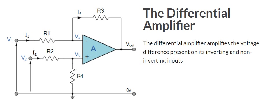 Image sourced from ElectronicsTutorials https://www.electronics-tutorials.ws/opamp/opamp_5.html
-
4\$\begingroup\$ Not entirely sure, but sounds like you need a comparator, not an opamp. Perhaps with a MOSFET to do the actual driving. \$\endgroup\$– winnyCommented Dec 1, 2023 at 12:06
-
\$\begingroup\$ As winny says, use a comparator. Is the unfused 12V available for your device, if not what power supply is? If so, connect the inverting input to a voltage divider which will give you about 11V, say 1K and 11K in series and the non-inverting input to the 12V fused supply via, say, a 1K resistor. The output of the comparator will then be high when the 12V is present and low when not. This assumes that the load on the fused supply will bring it to near 0V when the fuse blows. Then a simple bjt or mosfet can be used to power the LED via a suitable current limiting resistor. \$\endgroup\$– Peter JenningsCommented Dec 1, 2023 at 12:26
-
\$\begingroup\$ So is a comparator different to a op-amp? I bought an op-amp now so will it not work? I made a circuit that drops down a 48V source to 12V to be inputted with a voltage dividing circuit through a 10k ohm resistor into the non-inverting terminal. Then the reference voltage to be measured was inputted into the inverting terminal through a 10k ohm resistor. There is also a 20k ohm resistor in parallel at the non-inverting terminal. There is a resistor running from the inverting terminal to the output of the op-amp. The led is then in series with a 1220ohm resistor at the vout terminal. \$\endgroup\$– chambers02Commented Dec 4, 2023 at 6:38
3 Answers
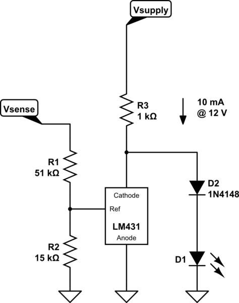
Riffing on Dave's answer, here's the low component way to turn an LED off when the sense voltage exceeds some threshold. Not for battery operation due to the continuous power drain, but 'fuse box' did sound like wall power was being used.
simulate this circuit – Schematic created using CircuitLab
Depending on the accuracy required, the 431 could be replaced by a simple N-BJT.
We don't know how low a plain 431 will pull its cathode down below its nominal 2.5 V, but a TLV431 will get to just below 1 V. Alternatively, add one or more diodes in the D2 position to increase the LED voltage above the on voltage of the LM431. Note that a white or blue LED will have well above the 431 on voltage.
-
\$\begingroup\$ I'm pretty sure that the LM431 can't pull its output below the Vf of the LED. \$\endgroup\$ Commented Dec 1, 2023 at 14:10
-
\$\begingroup\$ @DaveTweed Hmm, perhaps I was thinking of the LMV431 whose output will get to <1 V, and it will pull 20 mA. I'll modify the answer \$\endgroup\$– Neil_UKCommented Dec 1, 2023 at 14:16
-
\$\begingroup\$ @Neil_UK thank you. Ive simulated this with NGSpice using an npn bjt and it works when the supply voltage is around 38V. The only source I have for this supply is a 48V source. I tried dropping it down from 48 to 38 using a voltage dividing circuit but for some reason it drops the turn off voltage of the LED from just less than 12 to around 5V from the Vsense. Is there a simple low component way to drop this voltage down without changing the behaviour of the rest of the circuit. \$\endgroup\$ Commented Dec 4, 2023 at 14:21
-
\$\begingroup\$ @Neil_UK I changed the R1=42k ohms for the base current voltage divider and that solved the problem so I provide a 48V source to the Vsupply \$\endgroup\$ Commented Dec 4, 2023 at 14:44
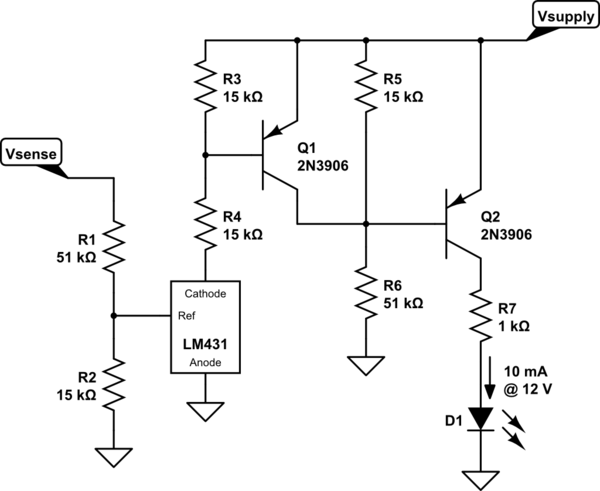
How precise does it need to be? The LM431 is a handy chip that includes both a voltage reference and a comparator. A couple of transistors can be used to switch the LED on:
simulate this circuit – Schematic created using CircuitLab
The LM431 sinks current if its Ref pin is greater than 2.5 V. R1 and R2 are selected so that this occurs when Vsense is 11 V. This turns on Q1 and keeps Q2 off. When the voltage drops, Q1 turns off and Q2 turns on.
The values for R3-R6 are not critical, so I used the same two values. R7 sets the LED current; adjust as needed for a different supply voltage or current value.
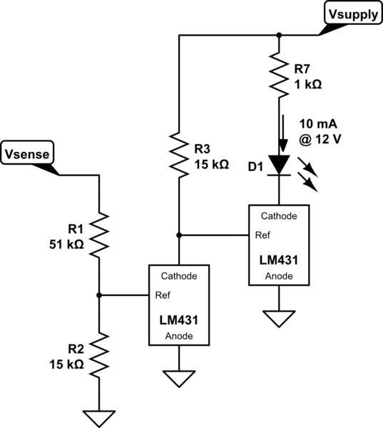
If you're willing to use two LM431s, the circuit can be simplified:
-
\$\begingroup\$ Are Q1 and Q2 really necessary? Figs 21 and 22 in the applications section of the data sheet you cite show voltage monitoring (which this is, essentially) with the LM431 driving an LED directly, via a current limiting resistor. If I read the data sheet correctly this current can be up to 150mA which is plenty for a single LED warning lamp. \$\endgroup\$ Commented Dec 1, 2023 at 13:22
-
\$\begingroup\$ @PeterJennings That only works if you want the LED on when the voltage is above the threshold. That isn't what the OP is asking for. I couldn't think of a way to reverse the operation with fewer than two transistors. \$\endgroup\$ Commented Dec 1, 2023 at 13:26
-
\$\begingroup\$ ... but yes, a second LM431 could be used to do that, too. \$\endgroup\$ Commented Dec 1, 2023 at 13:36
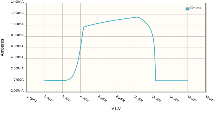
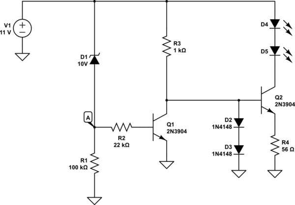
This design will switch on one or more LEDs with a reasonably constant current of 10mA, as soon as the supply voltage exceeds the LEDs' combined forward voltage. That would be 1.6V for a single red LED, for example, or about 4V for two green ones. LED current will be cut off when the supply voltage exceeds about 12V:
simulate this circuit – Schematic created using CircuitLab
Supply voltage on X, and LED current on Y:
Zener diode D1 ensures that the potential at A only begins to rise when the supply exceeds 10V. A volt or two beyond that, and Q1 switches on, shorting Q2's base to ground. That switches off Q2, cutting off LED current.
Use a different voltage-rated zener diode D1, to control the voltage at which cut-off occurs. For example, a 5.1V diode would cause cut-off to occur at around 7V.
Up until the cut-off point, Q2 operates as a poor-man's constant(ish) current sink:
$$ I_{LED} \approx \frac{0.6V}{R_4} $$

