advertised to be suitable for operation in the GHz range
Marketing will literally claim anything to sell an antenna; that's very much their job.
An antenna that doesn't come without a plot of efficiency over the relevant frequency ranges (or S11 or VSWR whatever sensible measurement relevant to you) should simply not get bought, no matter how cheap – anyone can sell you a piece of wet wood and claim it's an antenna for the 50 Hz – 12 GHz range. Promise!
Notice how even the reputable quectel antenna is sold as an antenna for frequencies up to 5 GHz – in whole bands this thing never gets better than 30% efficiency, see the image from the datasheet you linked to below. It's an antenna in these bands, alright, but is it a great antenna? No. Might a much smaller antenna have worked better, at least one band in isolation? Yes.

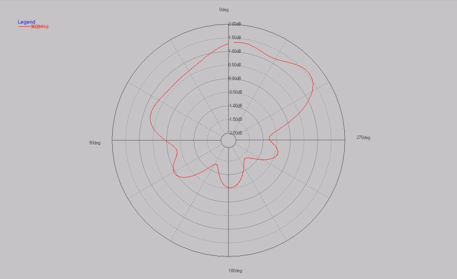
The radiation patterns, even for the lower bands, are surprisingly anisotropic, considering the device's symmetry.
My bet is on "used a rectangular ground (10 × 15 cm) plane sufficiently smaller than a wavelength for it to have effect on the antenna pattern"; that of course raises questions on the qualification of the tester.

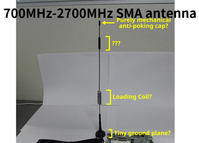
From my understanding, the coil is meant to be a loading coil that adds inductance to the circuit to cancel out capacitive reactance from a shorter length antenna (e.g., when the monopole is shorter than a ¼ wave).
Let's look at the one band that the quectel antenna is actually good in (VSWR < 2): ca 1.8 GHz to ca. 2.3 GHz. Wavelength at 2 GHz is 15 cm, quarter-wave monopole would hence be 3.75cm long. This antenna is much longer than the wavelength it works well at. So, for that band, the coil can't be used to electrically enlarge the antenna.
OK, so let's look at the lowest frequency they advertise, 700 MHz. Wavelength would be 42.9 cm, quarter of that would be roughly 10.7 cm. So, the antenna, being 28.5 cm long, is still much longer than that.
So, no. This is not an electrically short antenna.
The coil might be a mechanical element – to make this outdoor (and probably automotive-mounted) antenna resilient to wind load and vibrations.
Of course, the coil affects the behaviour of the antenna, and thus the electrical design was done around it. Or maybe it wasn't; after all, the antennna really isn't that great for a lot of the bands it gets advertised for. But I think it was – the antenna doesn't behave really badly anywhere in the intended band, and achieving that is also not easy.
So I think what happened here was a design process where the coil was included for mechanical reasons, and to make the antenna have different electrical lengths for different frequencies, and then the number of turns and the position of the coil was optimized to give an acceptable performance over the whole frequency range.
Small cap at the tip of the antenna. I assume this is purely for mechanical reasons, and doesn't have any significant electrical role?
yeah
Thicker section of the antenna. No idea what this is for. Maybe mechanical for wind-loading reasons?
that, or maybe some higher-\$\mu_r\$ material to, like the coil, make the antenna seem shorter for high frequencies, in order to achieve some "generally acceptable" design.
Pedestal which I assume acts like the ground plane, but it sure is tiny
The pedestal goes onto the ground plane, which the user has to supply, e.g. in the form of a metal car roof. (typically, the outer conductor of the coax feed is slightly coupled capacitively to that ground plane, but that makes surprisingly little difference in practice, in my experience).
How does such a long monopole operate in the GHz range efficiently?
It doesn't, aside from that one range, where the frequency-dependent behaviour of coil, "???" component and the monopole rod kind of compensate each other well.
Are there any general design rules for such an antenna, such that I can tell the antenna's operating frequencies/gain/etc from a few quick measurements, or build one for a specific frequency?
Since you have very few parameters to optimize:
- length of antenna
- turns of coil
- position of coil
- position of ??? component
you'd probably just go into your microwave design tool of choice, set it up to run a simulation over a few hundred sensible combinations of these parameters (VSWR of a single rod is not going to take extremely long to simulate in e.g. CST), come back the next morning, pick one or two of the best results, and if you feel like it, optimize that a bit finer.
Note that it's not easy to rule out that specific parameters where given in a non-electrical manner. For example, this being an automotive antenna, there might be end-user preferences for an antenna that looks like a high-quality antenna to someone who's not studied electrical engineering, i.e. a long rod, with something that looks like a coil.


