1
\$\begingroup\$

I have a project involving the following components:

The Setup:

The MCP3002 is connected to the Pi via SPI0 (pins 19,21,23,24), VREF is connected to 5V and VSS is connected to GND (pin 39) giving a 0V-5V range of measurement. CH0 is connected to the battery via the Bat pin (schematic here) of the 500C.

The Pi is powered by the PowerBoost 500C, which is a USB/Li-Ion battery power supply. The 500C is an all-on-one board using the TSP61090 with a female USB-A jack to power the RPi via the USB micro power jack.

The Problem:

When the RPi is powered on and running, everything works as expected. Reading the value of CH0 returns the correct voltage. However, when I shut down the RPi, I notice 60mA - 70mA of current flowing from the battery into the MCP3002. This clearly looks to be a problem that will drain the battery needlessly at best, and I suspect damage the RPi at worst. What is the right way to prevent this?

One idea (untested) would be to put a 47k resistor between the CH0 pin and the battery, reducing the current to 90uA. However, I am still unsure as to whether this is the 'right way' to setup this circuit. What is the right way to setup this circuit?

[EDIT]: Added the schematic below.

Note that the issue I am seeing is only when the RPi is off. The 500C is still providing power via the 5V pin.
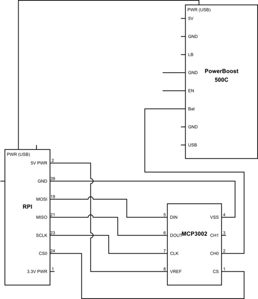
schematic

simulate this circuit – Schematic created using CircuitLab

\$\endgroup\$
1
  • 1
    \$\begingroup\$ Can you edit the question to include a schematic of the the components are connected together. Without the schematic I'm not sure, but CH0 is connected to the battery via the Bat pin (schematic here) of the 500C and One idea (untested) would be to put a 47k resistor between the CH0 pin and the battery, reducing the current to 90uA make it sound like the MCP3002 (and possibly other parts of the circuit) are being powered via the input protection diodes in the MCP3002 - see FIGURE 4-1: Analog Input Model in the data sheet. \$\endgroup\$ Commented Dec 19, 2023 at 7:31

1 Answer 1

2
\$\begingroup\$

However, when I shut down the RPi, I notice 60mA - 70mA of current flowing from the battery into the MCP3002.

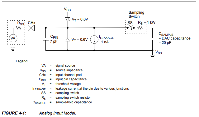
The MCP3002 Datasheet has the following which shows the input stage for one ADC channel:

enter image description here

Note the two input protection diodes between the CHx channel input and the VDD and VSS supply rails. Such diodes are normally intended to only conduct (briefly) to protect against ESD.

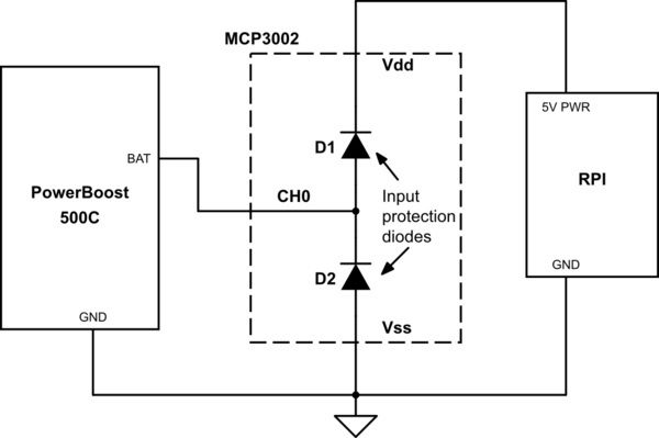
The resulting combination for the power rails is the following, which shows that when the RPi is shutdown BAT will power the RPi and MCP3002 via the input protection diode D1. The RPi 5V PWR and MCP3002 VDD will be the battery voltage minus the 0.6 V forward biased voltage drop of the input protection diode:

schematic

simulate this circuit – Schematic created using CircuitLab
This clearly looks to be a problem that will drain the battery needlessly at best, and I suspect damage the RPi at worst.

It will also be causing the MCP3002 input protection diode to conduct 60 mA - 70 mA continuously, and so may also damage the MCP3002. The MCP3002 datasheet doesn't provide an absolute maximum rating for the input protection diodes, but for other devices where the datasheet does provide an absolute maximum rating it is usually only a few milliamps.

One idea (untested) would be to put a 47k resistor between the CH0 pin and the battery, reducing the current to 90uA.

Yes, a series resistor would reduce how much current could be sunk through the MCP3002 CH0 input when the RPi is off.

However, I am still unsure as to whether this is the 'right way' to setup this circuit.

An alternative could be use an analogue switch between the PowerBoost BAT and MCP3002 CH0 input. Where the analogue switch would only be on when the RPi is powered and the software wants to take a battery voltage measurement. A GPIO output from the RPi could be used to control the analogue switch.

Not sure about using discrete FETs to create an analogue switch, but there are some ICs such as the ADG7421F Low Voltage Fault Protection and Detection, 12 Ω RON, Dual SPST Switch which will be off (leakage current in nano-amps) if no power or the enable input is a logic zero:

When no power supplies are present, the switch remains in the off condition, and the switch inputs are high impedance.

The switches turn on with a Logic 1 input and conducts equally well in both directions with an analog signal range of VSS + 0.1 V to VDD − 0.55 V for a 5 V single supply. The digital input is compatible with 1.8 V logic inputs over the full operating supply range.

\$\endgroup\$
1
  • \$\begingroup\$ This makes a lot of sense. Thanks. \$\endgroup\$
    – Ryan S
    Commented Dec 20, 2023 at 23:14

Your Answer

By clicking “Post Your Answer”, you agree to our terms of service and acknowledge you have read our privacy policy.

Not the answer you're looking for? Browse other questions tagged or ask your own question.