0
\$\begingroup\$

I have a PCB that has a 3.3V MCU working with a 5V CPU. I am using the TXS0104B to level shift certain signals coming out of the MCU going to the CPU. I would also like my board to function properly if the MCU is not installed. Right now, the MCU must be on and pulling one of the critical outputs low for proper operation. I though that I could just simply add a 10K or 4.7K pull-down resistor to the output line of the MCU and this would allow the line to go low if the MCU was not installed. However, I do see a voltage on this pin when using the pull-down resistor. It is acting like there is another pull-up resistor in the circuit and I am doing voltage division rather than getting my pin to GND.

After further investigation my theory is that the TXS0104B is not allowing me to pull the pin to GND. I also have a TXB0401B in the lab and tried it out on a breadboard, and I seem to have the same issue in trying to pull-up an input to 3.3V using a resistor.

How can I solve this such that I get proper voltage shifting but also can use pull-up and down resistors as needed for default situations?

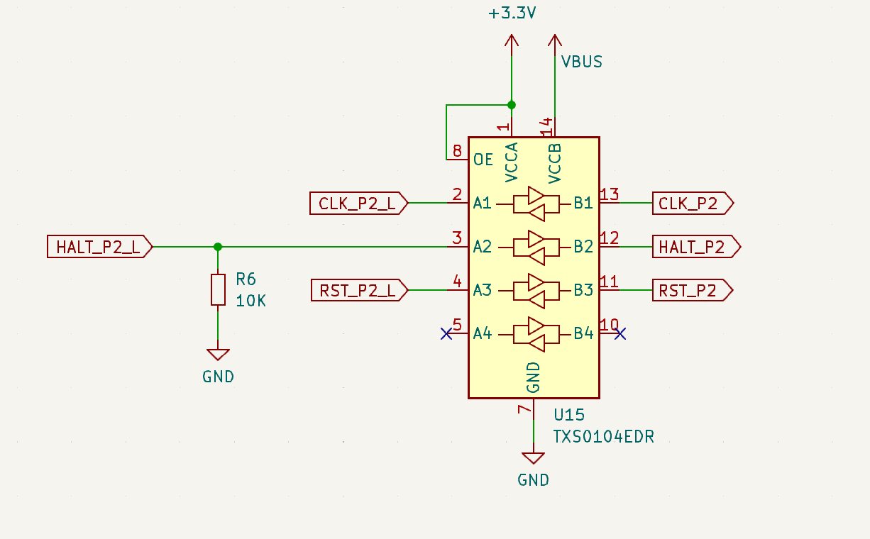
Here is the scenario that does not work. The signal HALT_P2_L can be driven by an MCU, or the MCU can be removed. I was thinking this would be the solution, but my testing and description above indicates otherwise. enter image description here
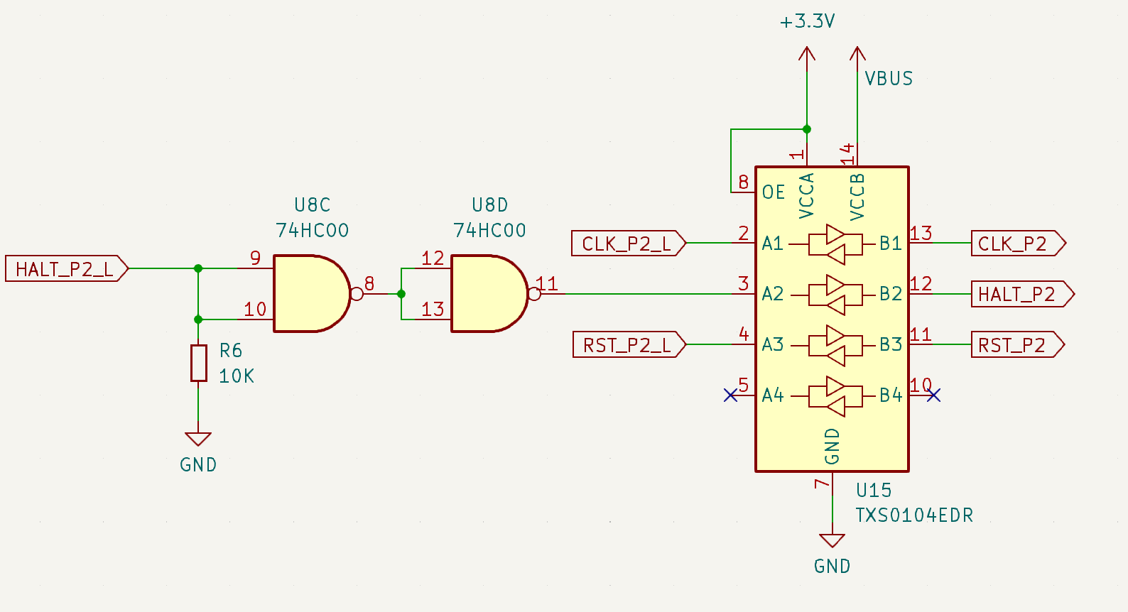
I have two unused NAND gates so I am thinking that this will work. enter image description here
\$\endgroup\$
5
  • \$\begingroup\$ Searching on these devices here will reveal no end of confusion and pain with them; this is probably a duplicate question. They are in general best avoided until one knows exactly what they're doing. \$\endgroup\$ Commented Jan 17 at 15:49
  • 1
    \$\begingroup\$ Use unidirectional level shifters, not "I trust that the chip will magically detect the direction" \$\endgroup\$
    – Ben Voigt
    Commented Jan 17 at 16:09
  • \$\begingroup\$ which do you suggest @BenVoigt \$\endgroup\$ Commented Jan 17 at 16:11
  • 1
    \$\begingroup\$ For example for a single channel, 74LV1T02GWH would be good. For multiple signals, MAX3004 family (part numbers from 3004 to 3012 depending on how many signals translating up and how many translating down) \$\endgroup\$
    – Ben Voigt
    Commented Jan 17 at 16:18
  • \$\begingroup\$ But only you have the details (max data rate, budget, etc) needed to select the "best" part for your circuit. \$\endgroup\$
    – Ben Voigt
    Commented Jan 17 at 16:20

3 Answers 3

1
\$\begingroup\$

While some of the level shifters from TI have built in pull ups, this one does not. It has a fet that facilitates transistion times by turning on for a period of time to help the transition.

On the output of the buffer there is 4k of resistance.

The datasheet shows what voltage level you'll get if you do use a pull up/pull down

enter image description here

How can I solve this such that I get proper voltage shifting but also can use pull-up and down resistors as needed for default situations?

Not sure, I'd have to see the circuit. One problem is these translators are finicky, and you need to make sure all of the voltage sequencing is done correctly. VCCa must always be more than VCCb even on startup, if it isn't the device will come up in a funny state. Also make sure no voltage is being applied to the ports, this also creates problems so all voltages should be zero before power up, I'm not sure if that's documented but it's one thing I've noticed with these devices.

Another thing: These devices only voltage translate and should be driven by an active GPIO anything else and it can create issues because of the bidirectional nature.

\$\endgroup\$
0
\$\begingroup\$

Either change to another level shifter that suits the purpose, or, drive the level shifter with a buffer IC, and have a pull-down or pull-up as you wish on the buffer input. Or just use the buffer without a level shifter.

\$\endgroup\$
1
  • \$\begingroup\$ That is helpful. Please see my update with new schematics in my original post. I'm thinking my new design would cure the issue without a lot of redesign and still using chips I already have on the board. \$\endgroup\$ Commented Jan 17 at 19:47
0
\$\begingroup\$

With these chips I spent like 2 days with 2-ch oscilloscope and adjustable resistor on every signal type I wanted to translate (my design is 5-25Mhz). Eventually I found a perfect formula for both side pullups, but ONLY experimentally. works now ROCK SOLID (I used 100MHz version)

\$\endgroup\$
2
  • \$\begingroup\$ And those results were--? \$\endgroup\$ Commented Jan 17 at 20:58
  • \$\begingroup\$ I got like 3 different values, depending on drive strength, push-pull/open-drain. Some pins were 200Ohms, others 680Ohms, others 2K. But I used to translate 1V2 <--> 2V5. All I'm saying - you better to hook it up to the scope. \$\endgroup\$
    – Sasha
    Commented Jan 17 at 21:35

Your Answer

By clicking “Post Your Answer”, you agree to our terms of service and acknowledge you have read our privacy policy.

Not the answer you're looking for? Browse other questions tagged or ask your own question.