2
\$\begingroup\$

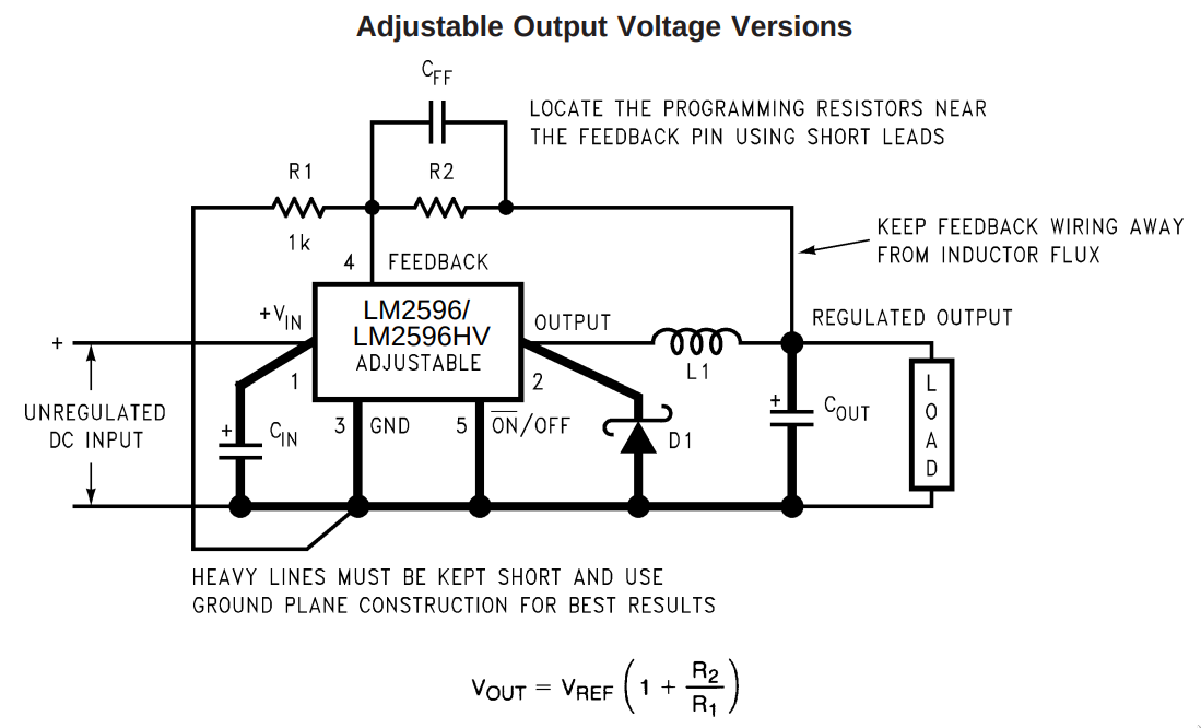
I am trying to replace R2 from this LM2596-based module for a MOSFET-based variable resistor:

enter image description here

According to this answer (https://electronics.stackexchange.com/a/15273/148272) it may be possible to use a low frequency PWM signal to vary resistance by varying the duty cycle.

My goal is to use an Arduino's relatively low PWM freq (~500 Hz) to achieve this and get rid of the pot.

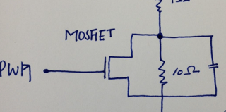
Other than just removing the trimmer I think I also need to remove \$C_{FF}\$ as per the info from this other question (PWM controlled variable resistance):

enter image description here

As shown, the job of the capacitor is to destroy the MOSFET. ie it is incorrectly shown.

Since the LM2596 works on the basis of very quickly (150 kHz) comparing the reference voltage (between R1 and R2) and adjusting the duty cycle so \$V_{OUT}\$ approaches the desired voltage, by switching R2 on and off the average resistance \$R_{AVG}=\frac{R}{D}\$ should do the trick, I think.

Would this work?

Other solutions I have explored include:

  • Turning the MOSFET into a variable resistor by operating it in the Ohmic region, by low-pass filtering the PWM signal to get a suitable DC for the gate. This dissipates a lot of power and might not even be that reliable, from other comments I keep reading around. Also JFETs are apparently more suited for this and I don't have any at hand to try.
  • Use an R-2R Resistive Ladder Network and use the Nano to select the desired R2. This works but is kinda wasteful.
  • Amplifying the PWM signal using a power MOSFET and low-pass filtering the output to DC. The problem with this is that for higher loads I will need to get a big (and costly) resistance (at least 6 W for my application) or putting a LOT (like 24) 0.25 W resistances in parallel to allow for a bigger load.

The load is a BLDC fan rated at 12V 0.5A, btw.

\$\endgroup\$
1
  • 1
    \$\begingroup\$ I would rather play on the low-side resistance \$R_1\$ which is ground-referenced and much simpler to control in my opinion than \$R_2\$. Also the FB pin is a sensitive input and should "see" a clean dc level otherwise instability may take place. A linear voltage-dependent resistance will be more appropriate than a "chopped" version I would say. \$\endgroup\$ Commented Jan 18 at 7:48

3 Answers 3

3
\$\begingroup\$

XY problem.

If you're controlling a 12V BLDC fan, get one that has PWM control built-in (that is, a 4-wire fan.) Unlike brush motors, BLDC motors don't tolerate the full range of lowered voltages, as they use a motor control IC to commutate the motor phases. (In my experience, the dropout voltage on a 12V BLDC fan is about 6-7V.) In contrast, with a 4-wire fan you only need to supply the PWM, and it can vary between 0 and 100%. Much, much easier and cheaper than using a controlled DC supply.

If you're determined to manipulate the DC voltage, read on.

First off, to be safer, use the low side resistor for this. Then as you decrease the resistor value, the output voltage increases. Also, you don't affect the feed-forward cap as much.

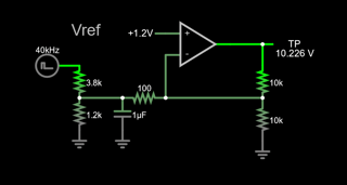
Second, how best to use PWM to control DC-DC? Typically, you will modulate the feedback node with an injected current. With a PWM control, such a circuit looks something like this (simulate it here):

enter image description here

The PWM will create a net current in or out of the feedback node. Current out of the feedback node will raise the voltage; current in will lower the voltage.

As shown, there's a voltage divider on the PWM which scales the PWM to the feedback voltage (1.2V). 100% duty cycle will be sourcing no current, resulting in the minimum output voltage (2.4V). Lower PWM duty cycles will sink current and raise the voltage, up to a max of 14.2V at 0% duty.

You can modify this behavior by changing the PWM divider resistor values, such that your output minimum voltage could even include 0V (make the divider's 3.8k to 3k for example, which yields a range from 0V to a bit below 15V.)

(Note: LM2596 Vref (feedback) voltage is 1.23V. Adjust accordingly.)

Could you use a FET modulated as a resistor? Sure, with some work. You could use a matched pair, and make a current mirror out of them with the reference current manipulated by PWM.

But to be honest, I've not seen this done since it's possible to do the same thing with just passives as I've shown above.

A more sophisticated approach is to use a pair of FETs as a charge pump. In this case you would control the duty cycle of each FET separately, to achieve a net current into or out of the feedback node. This can result in less noise on the output.

Finally, there is a better way. Maxim Integrated makes a line of current sink/souce DACs that are I2C controlled. They're designed for exactly this job. More here: https://www.analog.com/en/products/ds4422.html Then you avoid all the noise issues associated with PWM.

BONUS: If you need only a couple of specific voltages, I offer this suggestion: use several low-side resistors in series, and use FETs to selectively ground them. More here: Changing output voltage of a buck converter by electronically swapping the feedback resistors

\$\endgroup\$
9
  • \$\begingroup\$ Interesting, I didn't get far enough to explore the current sink/source solution to this, and it seems to be exactly the keywords needed to look for stuff like the DS4422 \$\endgroup\$
    – arielnmz
    Commented Jan 18 at 23:46
  • \$\begingroup\$ Yes. Nevertheless I still think you'd be better off changing to a 4-wire fan. This will cost less than trying to hack the LM2596, and you'll get a better result. \$\endgroup\$ Commented Jan 18 at 23:59
  • \$\begingroup\$ I salvaged this fan from a dead PSU, so I figured I could use it to move some air in my home lab rack by putting together a DHT11+this fan+an Arduino Nano somehow and learn more about electronics in the process. But I do agree, PWM is way easier. In fact, my first approach was to use an IRF520 and a 470uF cap to reduce the noise, then I went on to solve the problem of speed not corresponding linearly with PWM and here we are... \$\endgroup\$
    – arielnmz
    Commented Jan 19 at 2:13
  • \$\begingroup\$ By the way, I actually started exploring the idea of removing the feedback resistor network altogether and instead use PWM+Low pass filter to mimic the V_FB voltage and adjusting it from V_out via the analog input somehow... And it actually sounds a bit like the current sink/source you describe. Is that the case? Maybe I will ask a new question once I do the math for that approach. \$\endgroup\$
    – arielnmz
    Commented Jan 19 at 2:20
  • 1
    \$\begingroup\$ The resistor DAC approach can certainly work, and on the low side too. \$\endgroup\$ Commented Jan 20 at 23:52
1
\$\begingroup\$

I think you slightly misunderstood the answer you linked.

supercat does NOT say in his answer, that a low frequency PWM can be used - quite the opposite! The frequency of the signal over the resistor must be low in comparison to the PWM frequency! Or in other words: The PWM frequency must be significantly above the signal frequency.
The LM2596 uses 150 kHz switching frequency. Assuming a factor of 10 between signal freq and PWM would result in a PWM frequency of 1.5 MHz!

As Verbal Kint already mentioned in his comment, switching a FET referenced to ground is significantly easier than some higher (and variable) reference. So placing the FET between R1 and GND would be more reasonable. But you still need a pretty high PWM frequency. I doubt you can get 1.5 MHz out of the Arduino with any decent resolution. And a factor of 10 with 1.5 MHz might still be way to slow (too large a ripple) on the FB pin for stable operation.

\$\endgroup\$
2
  • \$\begingroup\$ Thank you for the answer. Please check supercat's last comment on their answer. I'm also confused what is this other low frequency signal you are referring to? \$\endgroup\$
    – arielnmz
    Commented Jan 18 at 16:20
  • \$\begingroup\$ I think I got it now, so the PWM approach could work because if the PWM freq is higher, the LM2596 won't pick those dips due to having a lower resolution, and to it, it would look like it's getting a net current corresponding a different resistance value, except maybe at the resonant frequencies (where the dips in both frequencies match). Am I correct? \$\endgroup\$
    – arielnmz
    Commented Jan 20 at 22:18
0
\$\begingroup\$

What you describe sounds far too complicated and I doubt it will work well, if it works at all.

I recommend you simply use a digital potentiometer to manipulate the feedback network - cheap and simple. There are several which come with an Arduino library.

\$\endgroup\$
4
  • \$\begingroup\$ Unfortunately, I haven't been able to source them locally in my country. Global marketplaces will take about a month and given how cheap they are I don't really want to spend 30x the cost for a couple in shipping fees nor order 100 of them... \$\endgroup\$
    – arielnmz
    Commented Jan 18 at 23:35
  • \$\begingroup\$ Couldn't edit my prev comment: what would be a good digipot for this application? \$\endgroup\$
    – arielnmz
    Commented Jan 18 at 23:42
  • \$\begingroup\$ That depends on the voltage range you want. There are also different options how it can be connected to the feedback network, each having a different transfer functions (voltage will not be linear). If it's for a 12V fan you probably don't actually need voltages below 5V(?). \$\endgroup\$
    – Sim Son
    Commented Jan 19 at 18:16
  • \$\begingroup\$ Note that I mean to add the pot to the feedback resistors, not to replace the resistors with a pot. Btw, 10 Ohm for R1 is faaar too low, the datasheet recommends values between 240 Ohm and 1.5 kOhm. You're probably also fine with 10 kOhm if it's just to drive a fan, but you shouldn't go lower due to unneccessary power dissipation. In case you didn't know: the outputcurrent does not flow through the resistors. \$\endgroup\$
    – Sim Son
    Commented Jan 19 at 18:21

Your Answer

By clicking “Post Your Answer”, you agree to our terms of service and acknowledge you have read our privacy policy.

Not the answer you're looking for? Browse other questions tagged or ask your own question.