0
\$\begingroup\$

I am trying to simulate a thermocouple amplifying circuit for a project, and for some reason, my output keeps producing a square wave, rather than a sinusoidal wave.

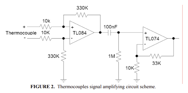
I found this diagram online on a published paper, and the group of people stated they used this circuit to amplify a signal, by reading a change in voltage through a thermocouple junction wire.

I am curious if this circuit is in fact not able to produce the amplified signal? Is it because the first op-amp is a "non-inverting amplifier" and the second is an "inverting amplifier", xo it's canceling the output signal?

Or am I simulating this circuit incorrectly? Do I need a variable DC source rather than a function generator? Variable resistors? Is R2 not supposed to be grounded? Is my V+ and V- power too low at 5 V?

I've tried a lot of these options and it's still producing a square wave. Please let me know, any advice is helpful.

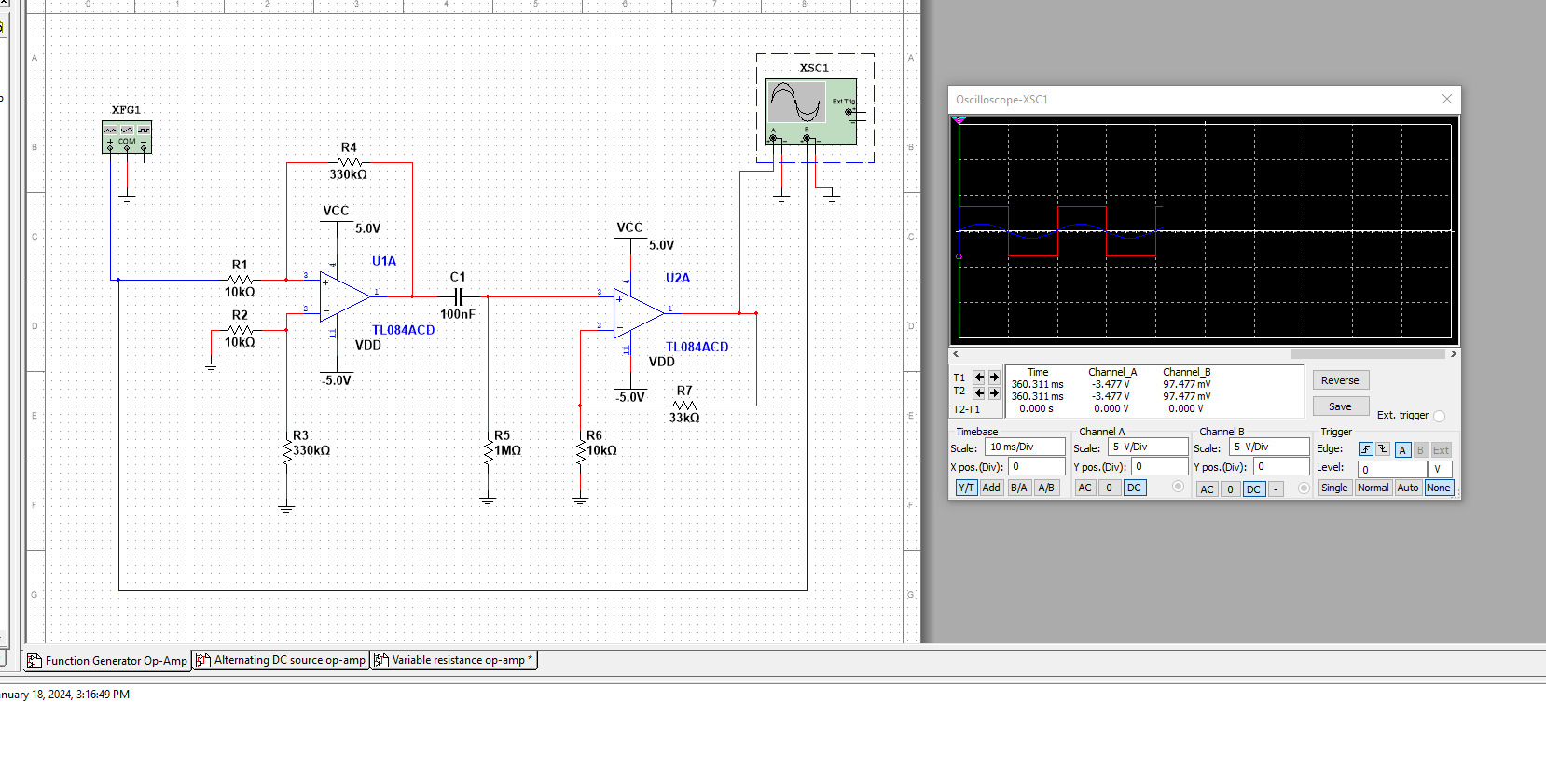
Multisim simulation. Blue is input, red is output

Thermocouple Circuit Diagram

\$\endgroup\$
3
  • \$\begingroup\$ Why do you expect a sine wave out of a thermocouple? \$\endgroup\$
    – AnalogKid
    Commented Jan 25 at 18:44
  • \$\begingroup\$ @AnalogKid Wondering the same thing, they have the two amplifiers coupled through a capacitor, so they must be expecting an AC signal. Not sure where the original circuit came from. \$\endgroup\$
    – GodJihyo
    Commented Jan 25 at 18:47
  • \$\begingroup\$ @kevin-martinez Can you give a source for the original circuit, we have some questions about it. Per site rules you have to cite any images that you got from another source. \$\endgroup\$
    – GodJihyo
    Commented Jan 25 at 18:49

3 Answers 3

1
\$\begingroup\$

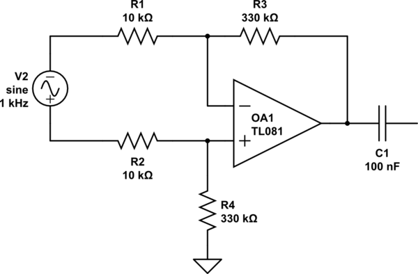
Edit: Just noticed, it looks like the first amplifier has the inputs reversed, the feedback resistor should be to the - input, not the +, as it is you have positive feedback which will cause the op-amp to saturate for a very small input signal. Try swapping them around. The rest of this is still pertinent though.

If you're expecting a sine wave and getting a square wave, that's usually an indication that you are overdriving an amplifier.

Judging from the resistor ratios it looks like the first op-amp has a gain of 33 and the second 3.3, so they likely designed it for a total gain of 100.

You have 5 V supply rails, so if the op-amps were ideal you could expect the maximum input before clipping to be $$ \frac{\pm5~V}{100} = \pm50~mV $$

and if I read your simulator correctly you've got near twice that.

With an op-amp like the TL084 the output won't reach the rails, so it will be less than that, which is why the square wave is only around \$\pm3.4~V\$. You would either need to reduce the input voltage or increase the supply voltages. Using a rail to rail op-amp would help as well.

Also in your simulation you are driving the input single ended, it should be differential. Try putting your voltage source across the inputs like this:

schematic

simulate this circuit – Schematic created using CircuitLab

\$\endgroup\$
1
\$\begingroup\$

The circuit was rather badly copied from this PhD thesis (E5) :

Sanderson, S. R., “Shock Wave Interaction in Hypervelocity Flow”, PhD Thesis, California Institute of Technology – Caltech, May 1995.

enter image description here

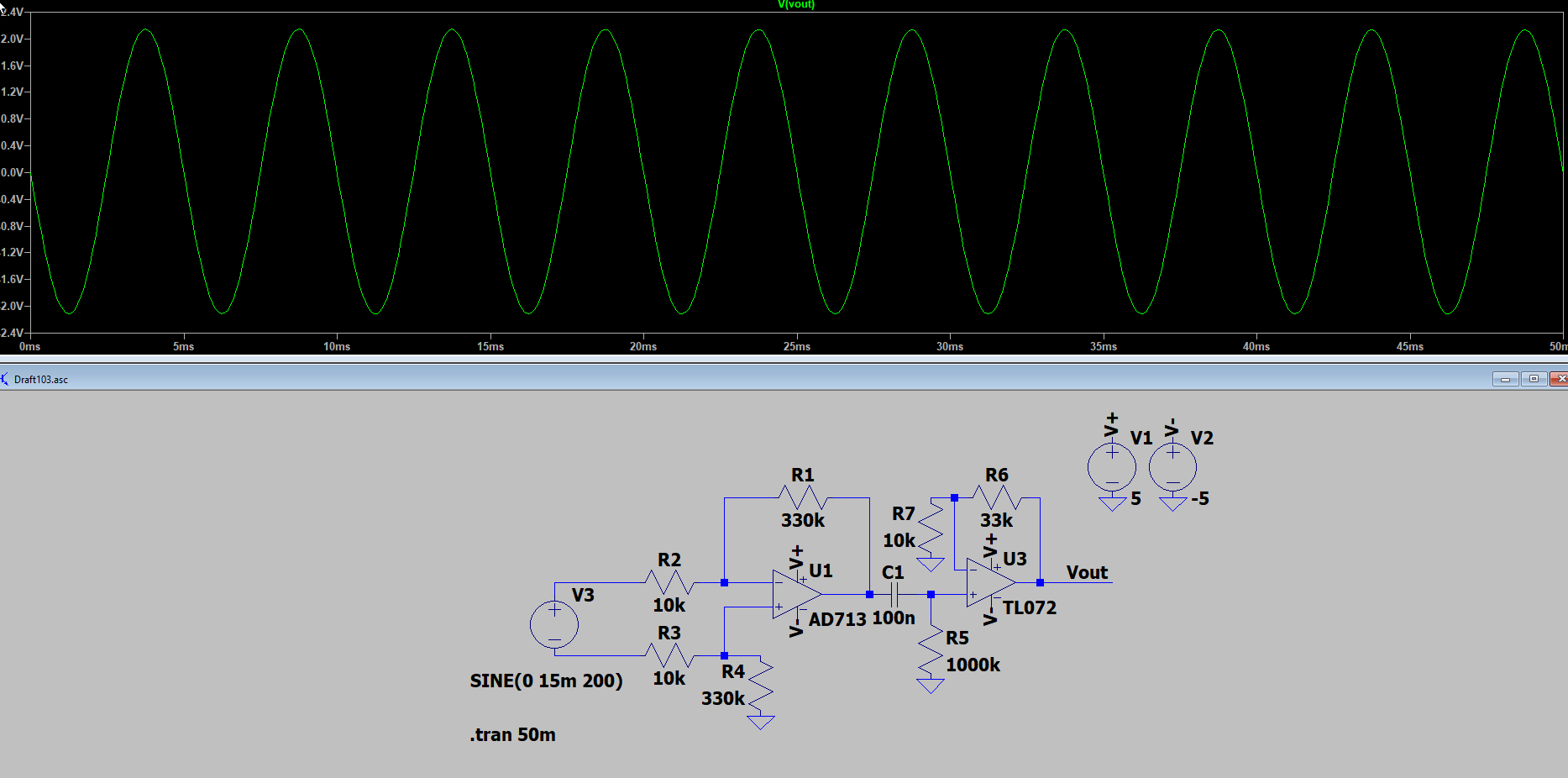
Note the correct negative feedback connections on the front end AD713. Your circuit is wrong (not an amplifier at all). Incidentally, the AD713 has 1/5 the typical voltage noise in the frequency range of interest compared to the TL084. The noise of the TL074 (which Sanderson used for the second stage amplifier) referred to the T/C input is not significant due to the AD713 gain.

In the original work, the thermocouple was of the Chromel-Constantan type, so a 200K temperature change would result in a signal of about 15mV at the input, so a couple of volts at the output.

Note that the input signal is a thermocouple with an ungrounded junction and thus is a floating voltage source wrt ground, and largely (within a few percent) a function of the temperature difference between the junction temperature and the cold junction temperatures.

Since the amplifier is AC coupled, the output will reflect rapid changes in the junction temperature provided the changes are short with respect to the 100ms time constant, the cold junction temperatures are stable, and the changes are not so rapid that amplifier gain-bandwidth or slew rates come into play. For that reason it's important that the correct alloy and polarity of extension wire be used to bring the thermocouple wires out to somewhere with a relatively stable temperature environment, as Sanderson did with the AWG34 PTFE twisted wires.

Here is a simulation with the AD713/TL074. Results would look very similar with the TL084/74:

enter image description here

\$\endgroup\$
0
\$\begingroup\$

Take note of the red writing on the image below: -

enter image description here

Same with this image: -

enter image description here

This is your problem. You have positive feedback and all bets are off.

\$\endgroup\$

Your Answer

By clicking “Post Your Answer”, you agree to our terms of service and acknowledge you have read our privacy policy.

Not the answer you're looking for? Browse other questions tagged or ask your own question.