0
\$\begingroup\$

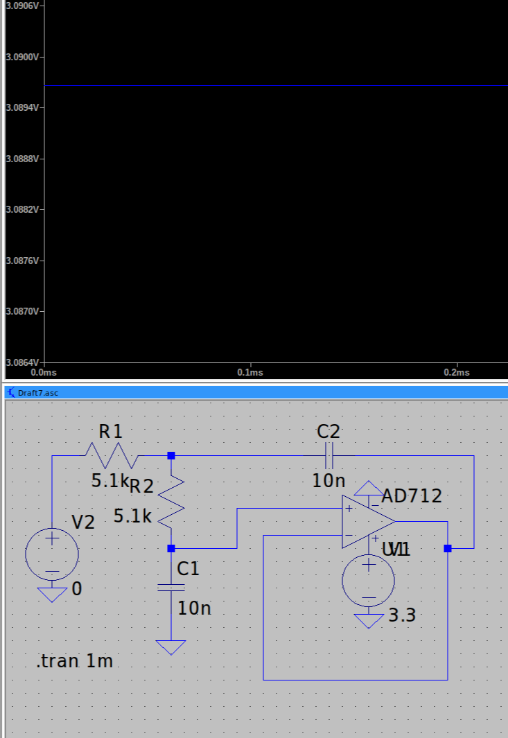
I was designing an active low pass filter for simple sigma-delta modulation signals. I found that the op-amp will output 3V when the input is 0V given that the power supply is 0~3.3V.

I simulate the circuit and find the same result. The circuit and the result are shown below. The blue line is the output of the op-amp.

simulation

According to my analysis, it is essentially a unity gain buffer with 10k2 input resistance in this scenario and the output should be 0V.

I noticed that the voltage will follow when V2 is slightly greater than 0V.

Why does that happen?

\$\endgroup\$

3 Answers 3

1
\$\begingroup\$

You are exceeding the input common mode voltage range of the opamp. The AD712 is designed to operate with a minimum of 10 Volt (±5 V). power supply.

You also have an input biasing problem. To get it to work with a single power supply, you need to bias the +input at half the supply. You can do this by adding a DC voltage source in series with V2.

For your experiments, use a ± power supply perhaps at ±5 V.

\$\endgroup\$
1
\$\begingroup\$

The first problem is you don't have an input voltage, it's zero volts. There are two ways to solve this. One is use a PWL source and use a step input (remember to use something like 10msec and 10.0000001msec for timestamps with the voltage of the first being 0 and the next being high (3.3V)).

The second problem is the simulation does a DC operating point, and so it runs the circuit and figures out the starting voltage. Sometimes it can get confused

"Ctrl-RightClick on the capacitor. In the SpiceLine cell, type "IC=0", for example, to set its initial voltage to 0V"

Changed 2V to 0V where applicable Source: How to define the initial charge of a capacitor in SPICE

You may also want to set the IC of the cap to 3.3V and leave the source at zero.

\$\endgroup\$
1
  • \$\begingroup\$ I have changed the "SpiceLine" to "IC=0" but the only difference is it rises to about 3V. The final result is still the same. And I observed the same in the real circuit when the input is 0V (i.e. the pulse density is 0 for the sigma-delta modulation signal). \$\endgroup\$
    – ONLYA
    Commented Jan 26 at 20:51
0
\$\begingroup\$

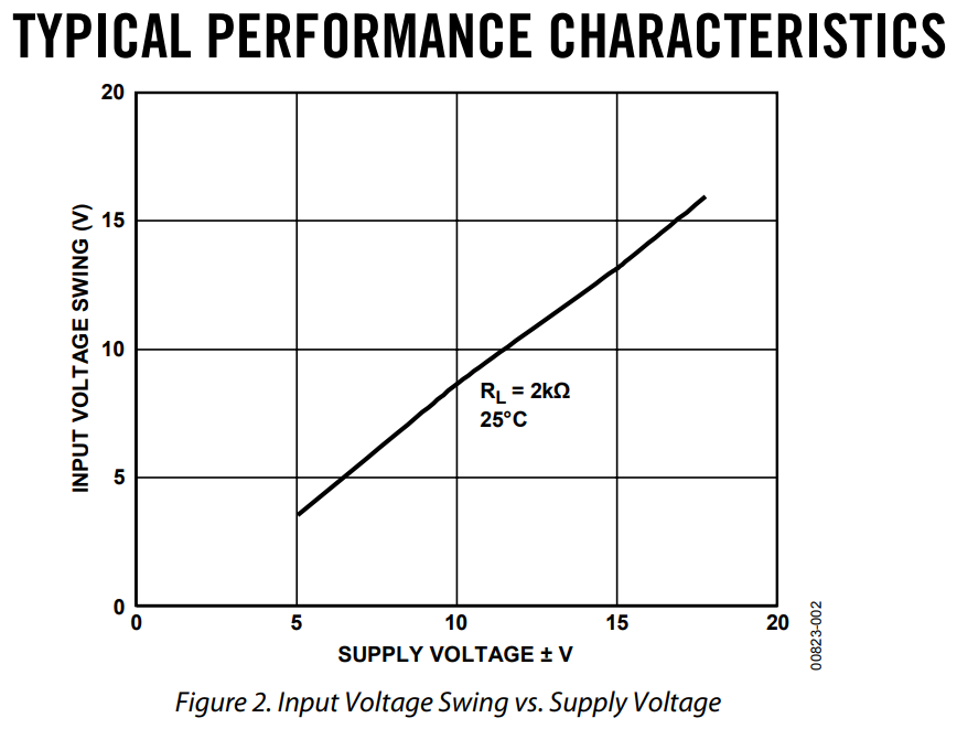
There are two things that can be taken from this graph in the datasheet: -

enter image description here

  • The minimum supply voltage is +/- 5 volts (a 10 volt span)
  • The valid input voltage range is about 3.5 volts for a +/- 5 volt supply

Additionally, the data sheets informs that the input voltage range is from +3.5 volts above the negative rail to 0.5 volts below the positive rail.

No-way will it work on a single 3.3 volt power rail.

\$\endgroup\$

Your Answer

By clicking “Post Your Answer”, you agree to our terms of service and acknowledge you have read our privacy policy.

Not the answer you're looking for? Browse other questions tagged or ask your own question.