1
\$\begingroup\$

I have what I hope to be a really simple question I have to ask now as it stopping me sleeping lol.

I’ve added Bluetooth to a 1950s car radio, using 2 SPDT switches (one could be replaced with SPST for power to be fair.) Anyhow, 1 switch basically gives power to the Bluetooth module when pressed in.

The other switch at the same time switches it from the Long/Medium wave audio signal to Bluetooth which is the two throws and the pole the audio output to the volume control.

The volume control knob I’ve had to replace because of space issues however would rather use the original switch as it has better range of control on it, which could be done if I only had 1 SPDT switch that I currently have. I’ve never used transistors before but I believe they can used a switches, and that I could potentially use the 5v supply being switched on as the signal to also switch the audio signal electronically? Replacing the need for an SPDT switch?

Can anyone give a diagram on how I would do this? As with the diagram I can learn alot for future projects and will hopefully understand.

Thanks in advance.

\$\endgroup\$
2
  • \$\begingroup\$ Please clarify your specific problem or provide additional details to highlight exactly what you need. As it's currently written, it's hard to tell exactly what you're asking. \$\endgroup\$
    – Community Bot
    Commented Feb 9 at 0:54
  • 1
    \$\begingroup\$ If you just want to combine the functions of the two switches, double pole double throw (DPDT) switches are available. \$\endgroup\$ Commented Feb 9 at 1:48

2 Answers 2

1
\$\begingroup\$

What you're describing is a so-called "analog switch". They're so common in audio circuitry (and other analog circuits as well) that they're available as ready-made chips which you just have to hook up to power and a control signal.

The DG419 is an example of a SPDT analog switch that might suit your needs. You need to give it a +/-5V (or higher, up to +/-15V) supply and then it operates as a switch controlled by a 0V/5V logic signal. It's also available in a DIP package, which you can easily solder by hand.

Don't forget to add bypass capacitors (i.e. 100nF) between the chip's power supply pins and ground, as close to the chip as possible!

\$\endgroup\$
1
  • 1
    \$\begingroup\$ This is exactly what I need! Thank you, I didn’t know these existed as I normally only repair broken components which is swap and replace so I’ve done here a big step out my comfort zone but it’s a learning curve and has been fun. I’ve ordered one of these and some extra components now, thank you again for your help 🙂. Sorry I can’t give rep as I’m too new 😔 \$\endgroup\$
    – Tom
    Commented Feb 9 at 7:37
0
\$\begingroup\$

I'm not sure I understood your requirements. I think you want a single switch to both control power to a bluetooth module, and change from radio to bluetooth audio.

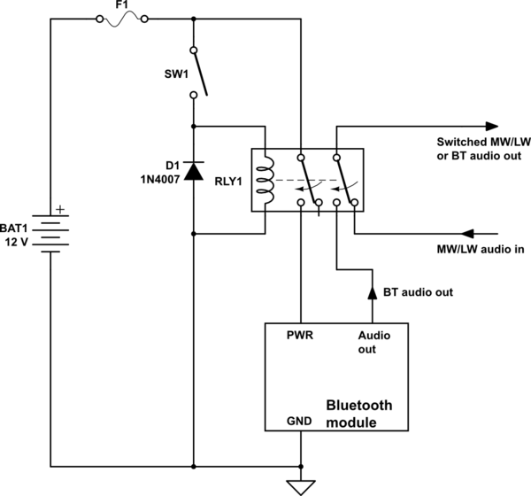
I know you asked for a transistor design, but that's non trivial. Instead here's a simple DPDT relay solution, which is more robust, and won't require complicated power supply conditioning to survive the evils of a typical automotive 12V supply:

schematic

simulate this circuit – Schematic created using CircuitLab

The relay coil is rated for 12V DC, your car's battery voltage.

This requires an SPST (SW1) to operate the relay coil, the relay does the rest. One pair of relay contacts controls power to the bluetooth module, the other controls which audio source is selected.

\$\endgroup\$

Your Answer

By clicking “Post Your Answer”, you agree to our terms of service and acknowledge you have read our privacy policy.

Not the answer you're looking for? Browse other questions tagged or ask your own question.