I'm trying to design a circuit to power my DIY analog synthesizer. My requirements are:
- 9V DC input voltage (from a common 9V wall adapter)
- +/-15V output voltage
- able to supply about 500mA on +15V and about 400mA on -15V
I selected this DC-DC converter series PDQE15-D as best candidate for the task.
My idea is to use two of PDQE15-Q24-S15-D, one for +15V and one for -15V.
Main specs are:
- 9~36 input voltage
- 15V isolated output, max 1000mA output current
- ±10% output voltage trimming
- 100mVp-p output ripple noise
since those DC-DC converters usually all have high ripple noise, and since my analog synthesizer wouldn't tolerate that (rail voltages are often directly used as frequency reference for the VCOs and other, so noise on the rails would result in frequency instability, for example), I thought about using a linear regulator after the DC-DC converter, that should reject enough ripple noise.
so the idea was to adjust the DC-DC output to ~16V and then use a LDO like the LM2940 to get a clean +15V output. The same will be done to get the -15V output, using another identical DC-DC converter and a LDO like the LM2990
I considered using the dual output +/-15V DC-DC converter of the same series, but the dual output variant can't be trimmed. So the next higher voltage available in the series would be +/-24V, but regulating that to +/-15V would result in too much heat wasted.
I choose the 15W series because even thought I only need 500mA for each rail, I guess the 15W DC-DC converter would not be stressed to its limit.
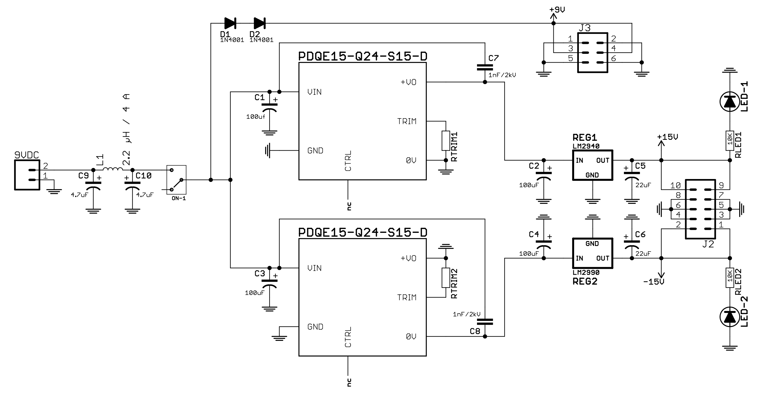
so far what I drawn is this:
- C9/L1/C10 are took from the EMC RECOMMENDED CIRCUIT on the datasheet, but I don't know if I got that part right
- the ON/OFF mechanical switch is simply removing the power from the converters, I'm not using the CTRL pins.
- should I worry about start up times?
- to get -16V, I simply wired the output of the second DC-DC converter in the opposite direction of how it is supposed to be wired.
- C7 and C8 are again took from the EMC RECOMMENDED CIRCUIT, but I'm not sure if C8 should be there or on the +VO pin.
side note: you can see an additional +9V output connector (J3), that one is needed to supply a 7805 regulator on a daughter board, D1 and D2 are probably not needed
what are your thoughts? I don't expect this to be an ideal solution, I guess a better solution would be to design a custom DC-DC instead of using an off the shelf DC-DC, but that goes beyond my capabilities

