4
\$\begingroup\$

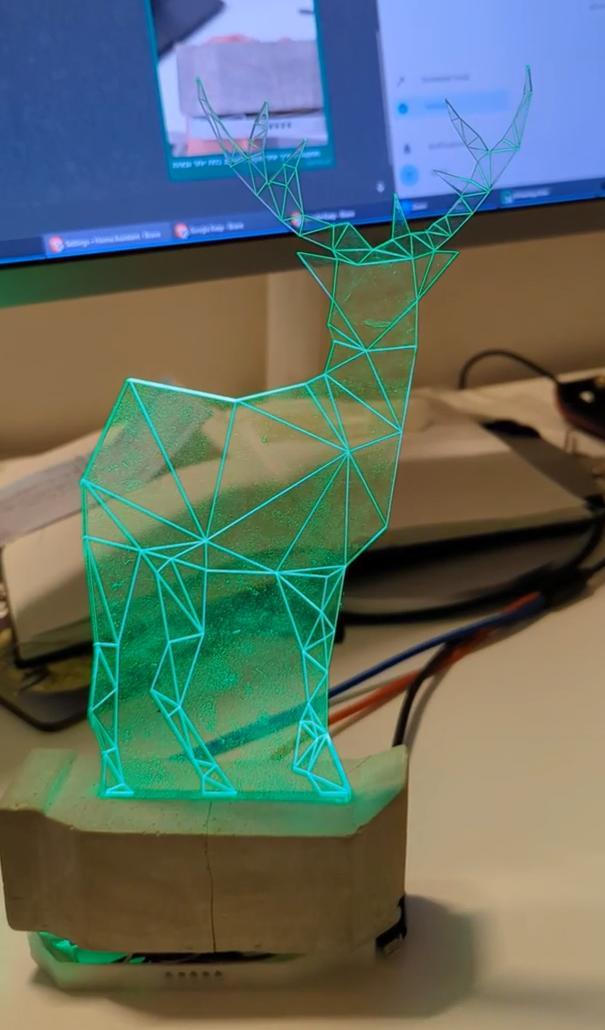
I'm working on an ESPhome project of a night light lamp for my young kids, which automatically glows in different colors to let them know when they're supposed to be already sleeping at night \ allowed to get out of bed in the morning.

enter image description here

Here's a video demo:

https://v.redd.it/link/1au2ss1/asset/gjdup17vdejc1/DASH_720.mp4

It also has a temperature sensor, intended to automate turning on/off a radiator when it gets too cold in their room at night.

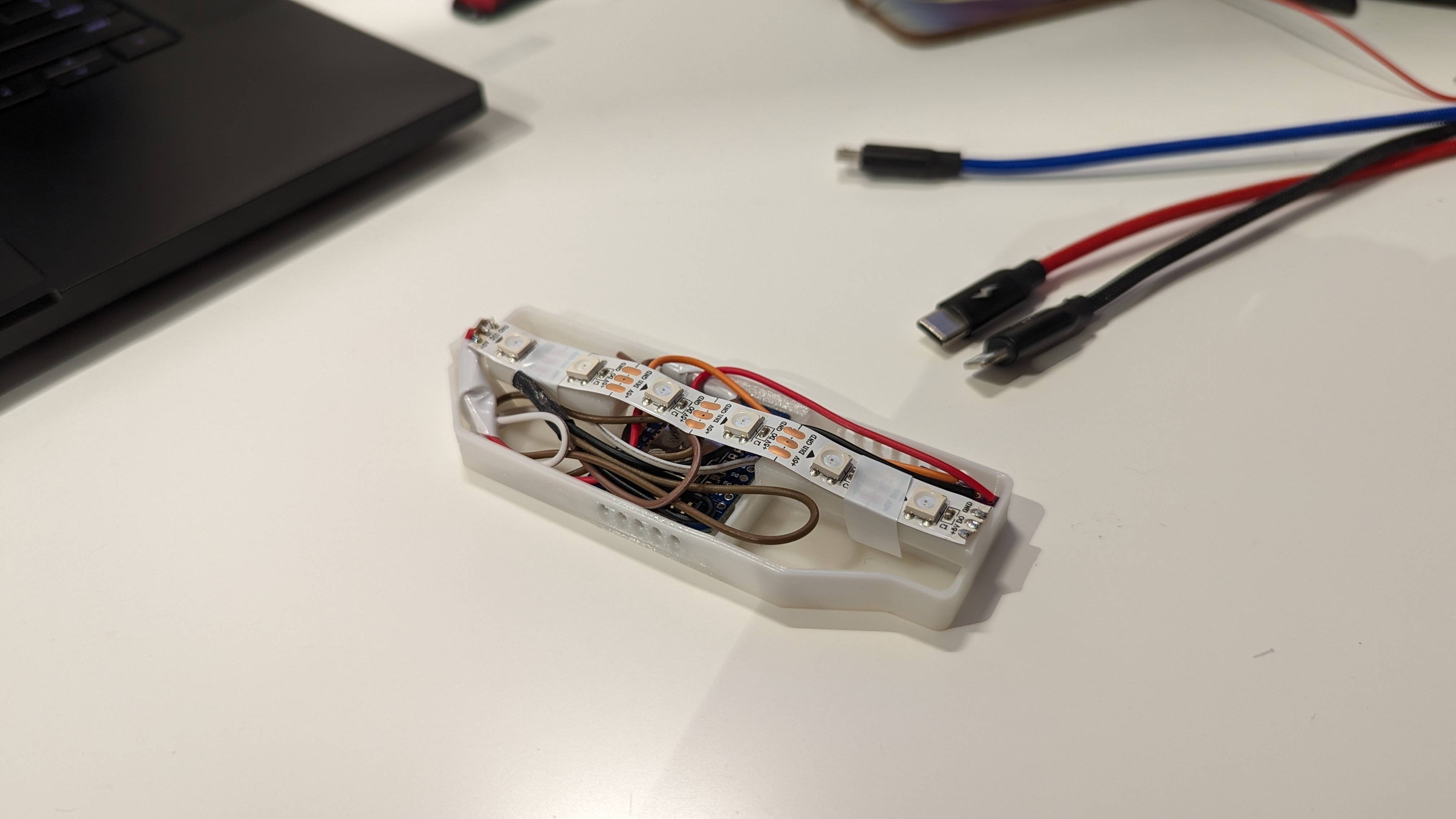
Essentially, it's a just a D1 Mini ESP8266 running ESPHome hooked up to 6 ws2812b LEDS and a BME280 I2C Temperature/Humidity sensor. The LEDS illuminate a plexiglass sheet that sits in a concrete molded fitting. The electronics are housed below in a custom 3d printed base. Everything is powered by a 2 amp 5V USB charger connected to the board.

enter image description here

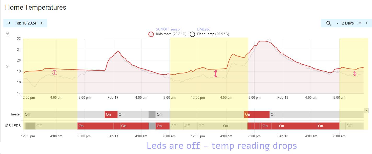
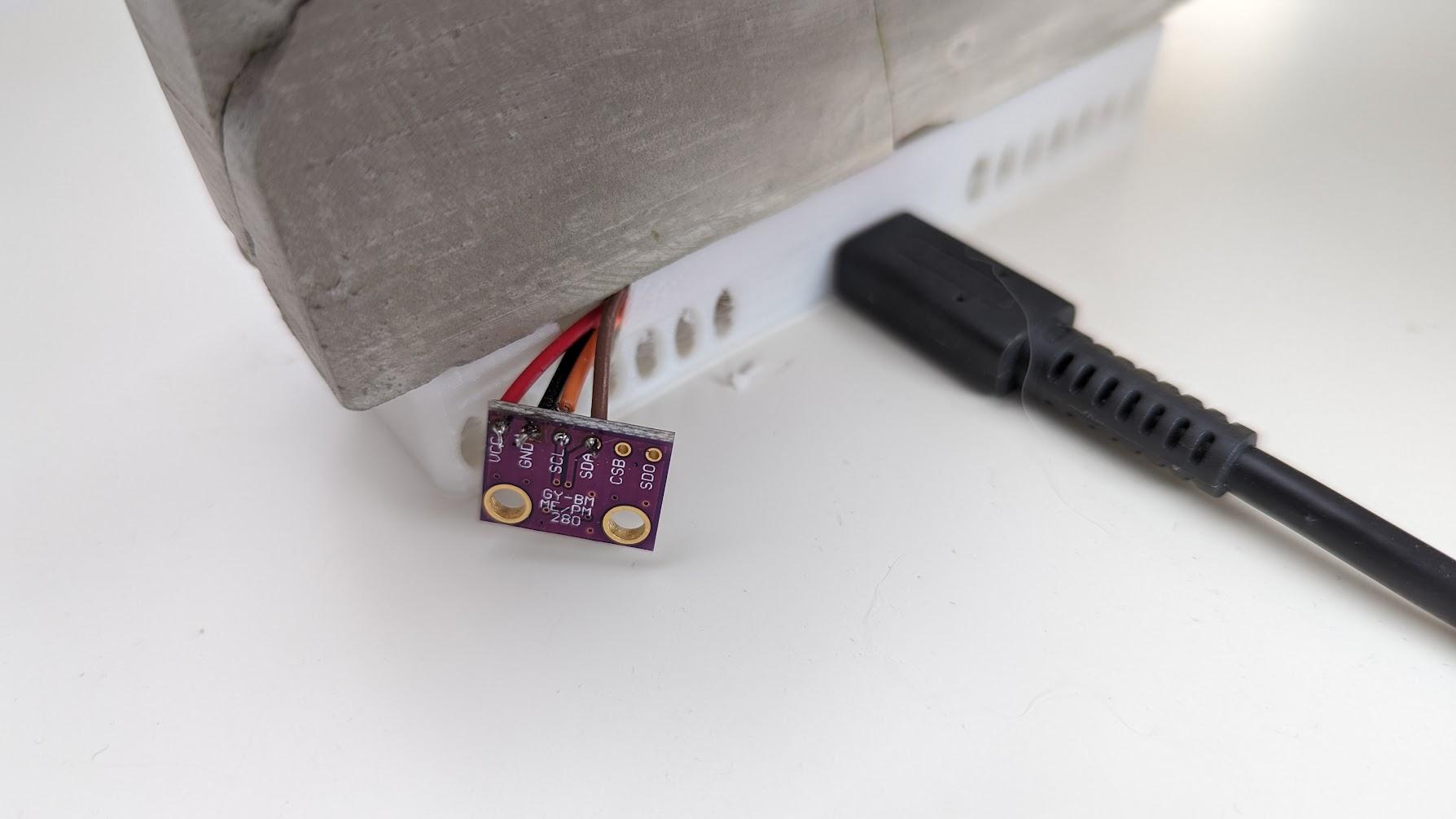
My issue is that the BME280 gives me different readings when the LEDS are on from when they are off (while they're static, ie not changing color). Specifically, I'm comparing its readings to a SONOFF SNZB-02P ZigBee Temperature/Humidity sensor that sits right next to it. (The BME280 is in the open air, next to the Sonoff and away from the LEDS so it's not affected by their heat). I know the BME280 reads a couple of degrees higher due to self heating (which I've set an offset for, but what I'm seeing is that it actually gives higher temperatures when the LEDS are on and lower when the LEDS are off. Here it is in the data:

enter image description here

Any clue why this might be happening and how to prevent the LEDS from affecting the sensor? To reiterate it's not the LED heat that's changing the reading since the BME280 is far away from those and sits right next to the SONOFF, which isn't affected.

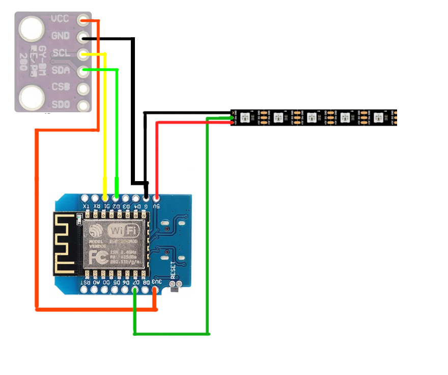
Here's how it's wired:

enter image description here

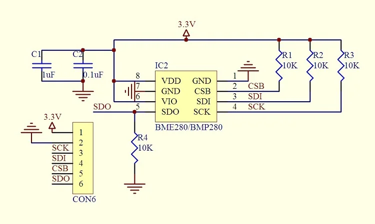
More information about the sensor module:

enter image description here

enter image description here

My intuition is that when the LEDS are on, there is some sort of voltage drop that affects the sensor reading. How would I go about avoiding it though? Is there a type of component I can add to the circuit to do so, and if so which, where and how should it be wired?

\$\endgroup\$
11
  • 1
    \$\begingroup\$ The sensor and LED strip are on different voltage rails, but I notice you are sharing the ground pin for the sensor and the LEDs, which is questionable. If you move the LEDs to the 5V supply directly so that their current does not return through the MCU, does the problem go away? \$\endgroup\$ Commented Feb 19 at 1:41
  • 1
    \$\begingroup\$ Suggest adding 100nF ceramic capacitors bypassing all three devices, ESP8266, BME280, and LED's. Meaning put one capacitor per device on the power-in, as close to each device as possible. \$\endgroup\$ Commented Feb 19 at 4:18
  • 1
    \$\begingroup\$ @MicroservicesOnDDD Appreciate the input! Clarified and added more information in the q. According to the spec sheet for the LEDS (added link to the q) "The data transfer protocol use single NZR communication mode". Discrepancy happens when is when LEDs are on and static. Temp sensor is i2c, read in Forced mode per section 3.3.3 \$\endgroup\$
    – OpherV
    Commented Feb 19 at 7:21
  • 1
    \$\begingroup\$ @OpherV my intuition still goes towards LED heat or air flow induced by LED heat affecting the bare PCB differently from the SONOFF protected in its case. Especially as your last photo shows the BME280 right next to the air vents of the base. \$\endgroup\$ Commented Feb 19 at 8:17
  • 2
    \$\begingroup\$ The wiring from the MCU to the BME280 may also be a source of heating (as a heat conductor). This is my experience with similar sensors. Try longer wiring to the sensor and keeping it as far away from the main body of the night light (as far as practically and aesthetically feasible). \$\endgroup\$
    – StarCat
    Commented Feb 19 at 8:20

5 Answers 5

4
\$\begingroup\$

By the current information from the post and comment, I still not able to conclude the mechanism and solution for this problem. As it might take a lot of time and effort to fully understand everything, I suggest another way around which I called it black box problem solving.

As the problem was coupling between LED and temparature sensor reading, my assumption are as following.

  1. Physical coupling there is real hot-air at the sensor but the control-sensor doesn't pick up
  2. Electrical coupling as OP suggest. the voltage signator of LED might affect the sensoe reading either from sensor side or MCU side.
  3. Software coupling the LED and sensor code might intervene each other.

Even my assumptions are ridiculous but I don't want to cut the possibillity as we dealing with mtsterious things we need to think outside the box.

Next, to verify the assumption I've design the experiment as follows.

  1. Keep everything but used difference power supply for LED to see effect of PSU.
  2. Keep everting the same but separate MCU, one for LED only and one for temp sensor (with same PSU) to see effect of software intervention
  3. (Optional) Change to position of sensor, to see effect of positioning.

As you following these step, your problem might fall into one of three assumptions. So we can moving on from that.

\$\endgroup\$
3
\$\begingroup\$

Just by looking at the pictures, the following is quite hard to believe:

The BME280 is in the open air, next to the Sonoff and away from the LEDS so it's not affected by their heat

The wires to the BME280 module go right next to the LEDs. The wires are extremely short between the sensor and LEDs.

The LEDs will heat the wires and the wires conduct the heat to the BME280 board.

Conducted heat through the wires will easily explain a temperature rise of less than 1 °C when LEDs are on.

You can easily verify this by putting longer wires or routing the wires in a better way that they cannot heat up with the LEDs.

\$\endgroup\$
1
  • \$\begingroup\$ Thanks, that makes sense. I haven't considered heat transfer via the wires themselves over time. I will attempt your suggestion that to confirm/rule out this cause \$\endgroup\$
    – OpherV
    Commented Feb 19 at 11:24
2
\$\begingroup\$

Your graph is showing gradual convergence / divergence between the sensors over a period of 10-20 minutes; this points towards a thermal effect not electrical. Out of the top of my head, I see three possibilities.

  1. If the last photo is representative of your setup, I would say that although it's out of the case, you still have the BME280 positioned very close to the LEDs, and also in the path of the airflow in/out of the case. To rule out heating caused by the LEDs, I would position it at least a good 20cm away and even put a physical barrier between it and the sculpture.

  2. If your software samples at a different rate when the LED is on/off, this could change the amount of self-heating in the sensor.

  3. Your graph has the LED on/off periods at fixed times of the day. That makes it correlated with human activity and sunlight. So it might be that there is more air turbulence when humans are moving around or there's more convection currents in the room when the sun is out and the extra airflow dissipates more of the BME280's self-heating. The SONOFF sensor would be less sensitive to this if it's protected in a case. This would explain why the divergence between the two sensors seems to start slightly before the LEDs go off. But with only two day/night cycles on the graph there's not enough data to tell if this is a coincidence.

\$\endgroup\$
1
\$\begingroup\$

TL;DR: The sensor should be thermally decoupled from where the LEDs are, that's about it. It gets warmer when the LEDs are on, whether by conduction, convection, or a mix of both.

It quacks like a duck, let's make sure it's not a duck. LEDs generate heat. Sensor registers higher temperature when the LEDs are ON. Occam's razor: sensor actually gets hotter. Try to address the simplest explanation of what's going on first.

Sure, there is a possibility that this is some sort of interference from the PWM on the LEDs. To check that, measure how much power the LEDs dissipate, and solder a resistor that will dissipate same power where the LEDs were. I bet you the sensor will still measure higher temperature. Then you'll confirm that there's nothing LED-specific about the effect, but rather just plain old heating.

To understand how sensitive the LEDs are to conduction via the wires, grab the middle of the length of the sensor wires with your hand, and look at temperature readings. In a couple minutes you should see at least 1C higher if not more.

\$\endgroup\$
1
\$\begingroup\$

I don't think the effect is related to the LEDs at all!

In 2 of the 4 light transitions you illustrated (where the effect grows) the temperature deviation starts before the light actually transitions. In the other two transitions - where the effect shrinks - it's just hard to tell. If the time accuracy of your data is not totally bad, this observation on its own is quite evident, in my opinion - an effect just can't happen before its cause.

Beside that, the temperature deviation starts at 8 am and ends at 8 pm consistently, at least in the provided data. Very suspicious...

I bet this effect is caused by the environment and it might be anything like:

  • (different) exposure to sun light between sensors
  • some heater being activated during day/night (maybe even only your neighbours heater behind a wall)
  • some window is opened during day/night
  • does the SONOFF sensor have a display with backlight? (-> does illumination/self-heating depend on ambient brightness?)
  • ...

After all we don't actually know whether the BME280 or the SONOFF sensor is "off" ;)

To me it generally doesn't look like a problem with software nor hardware, but definitely like a thermal effect. "Thermal" can be many things and doesn't mean it's caused by your system itself.

Things I would test:

  1. disable the LEDs in software or disconnect them so they are off. Leave everything else unchanged. Observe the system over the period of a day or two and see if it makes a difference.
  2. put all the stuff into a box or otherwise isolate the whole system from the surrounding as good as possible. This way you should be able to decide whether the effect is caused "from outside or inside".
\$\endgroup\$

Your Answer

By clicking “Post Your Answer”, you agree to our terms of service and acknowledge you have read our privacy policy.

Not the answer you're looking for? Browse other questions tagged or ask your own question.