1
\$\begingroup\$

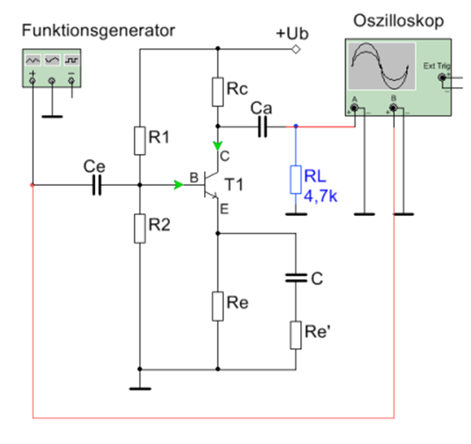
I am working on an emitter circuit that has a 2N3904 NPN transistor.

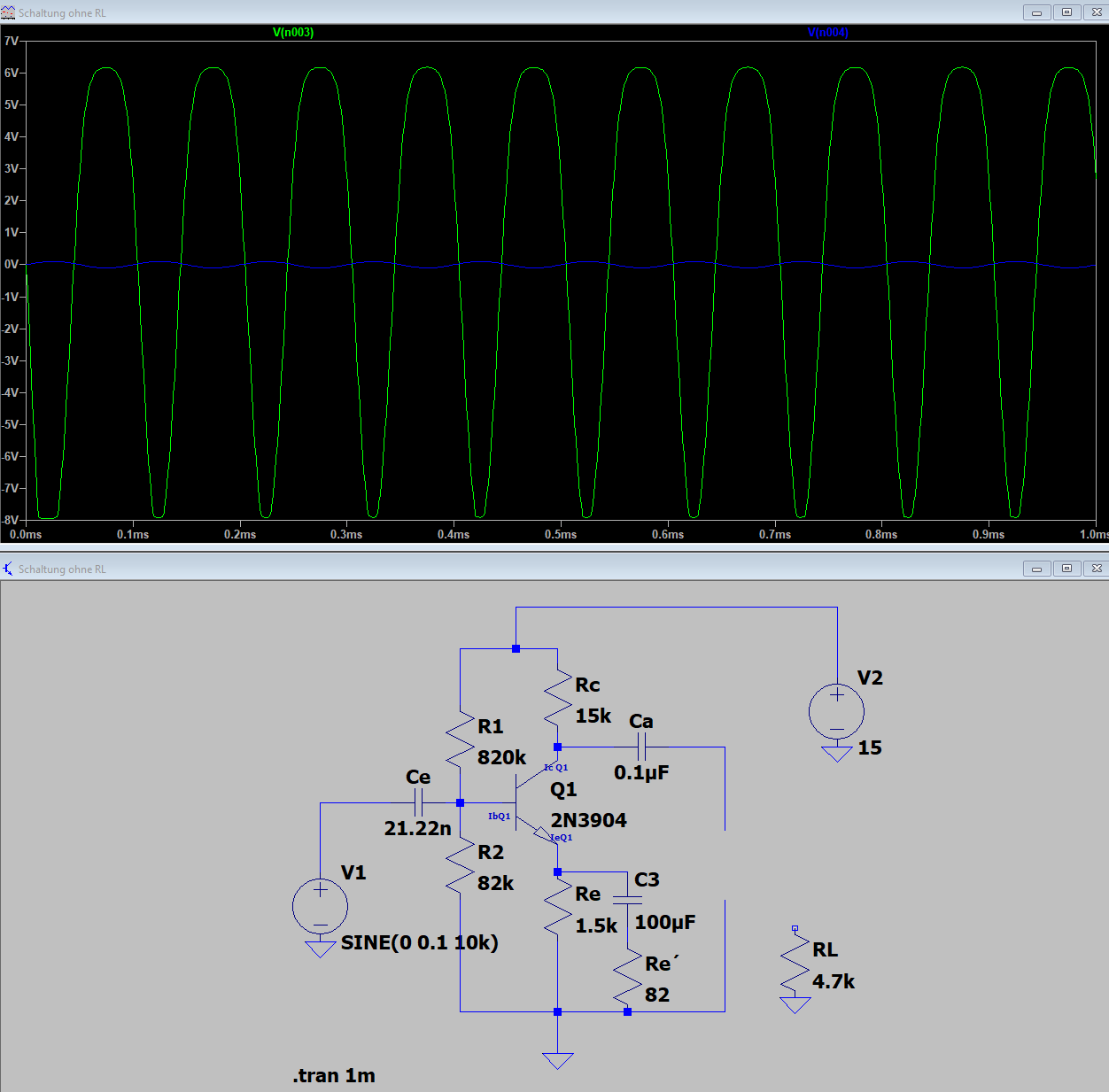
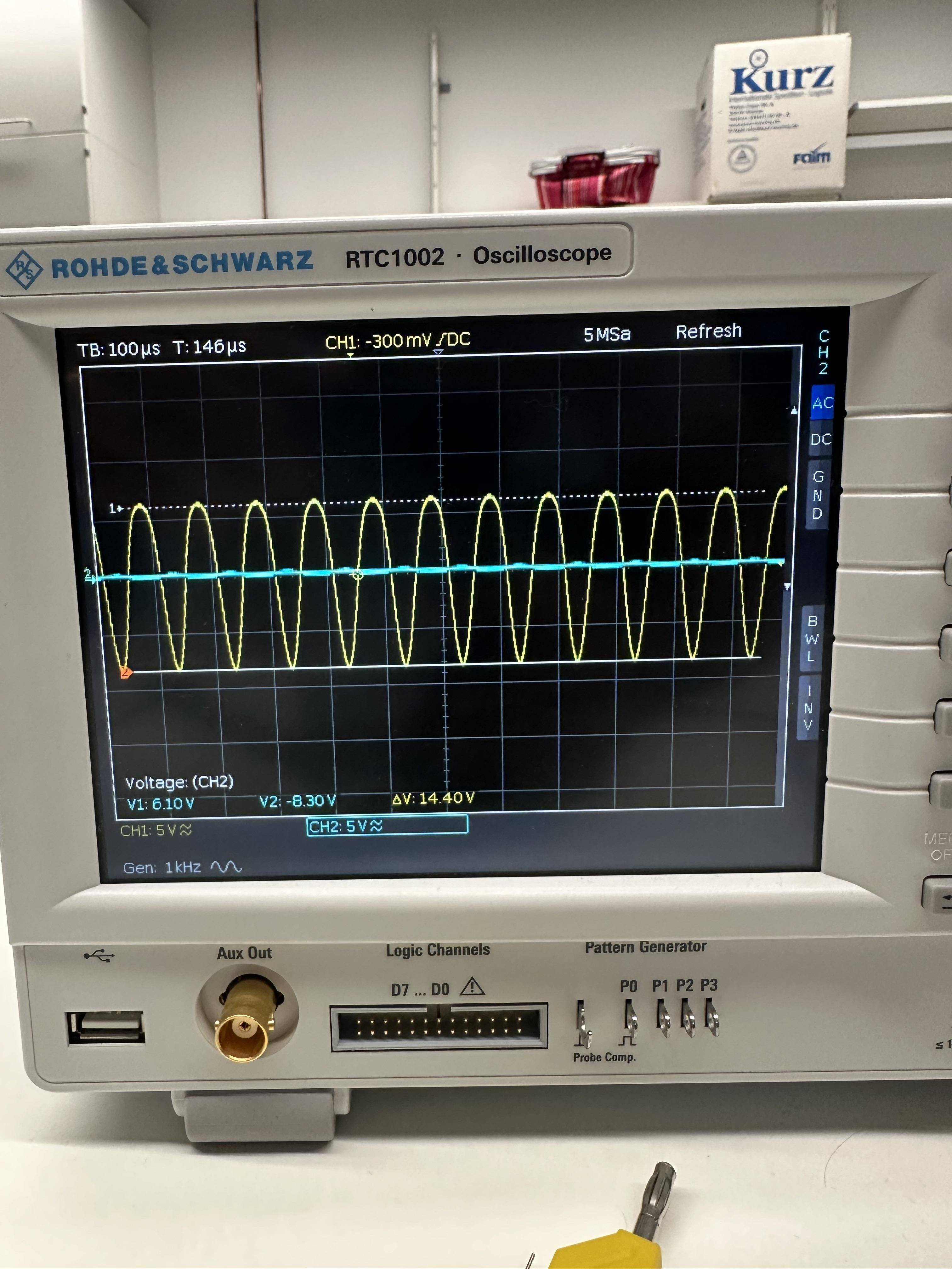
I have simulated the circuit before and got the results. I am trying to build it in the lab so I can compare the results to my simulation.

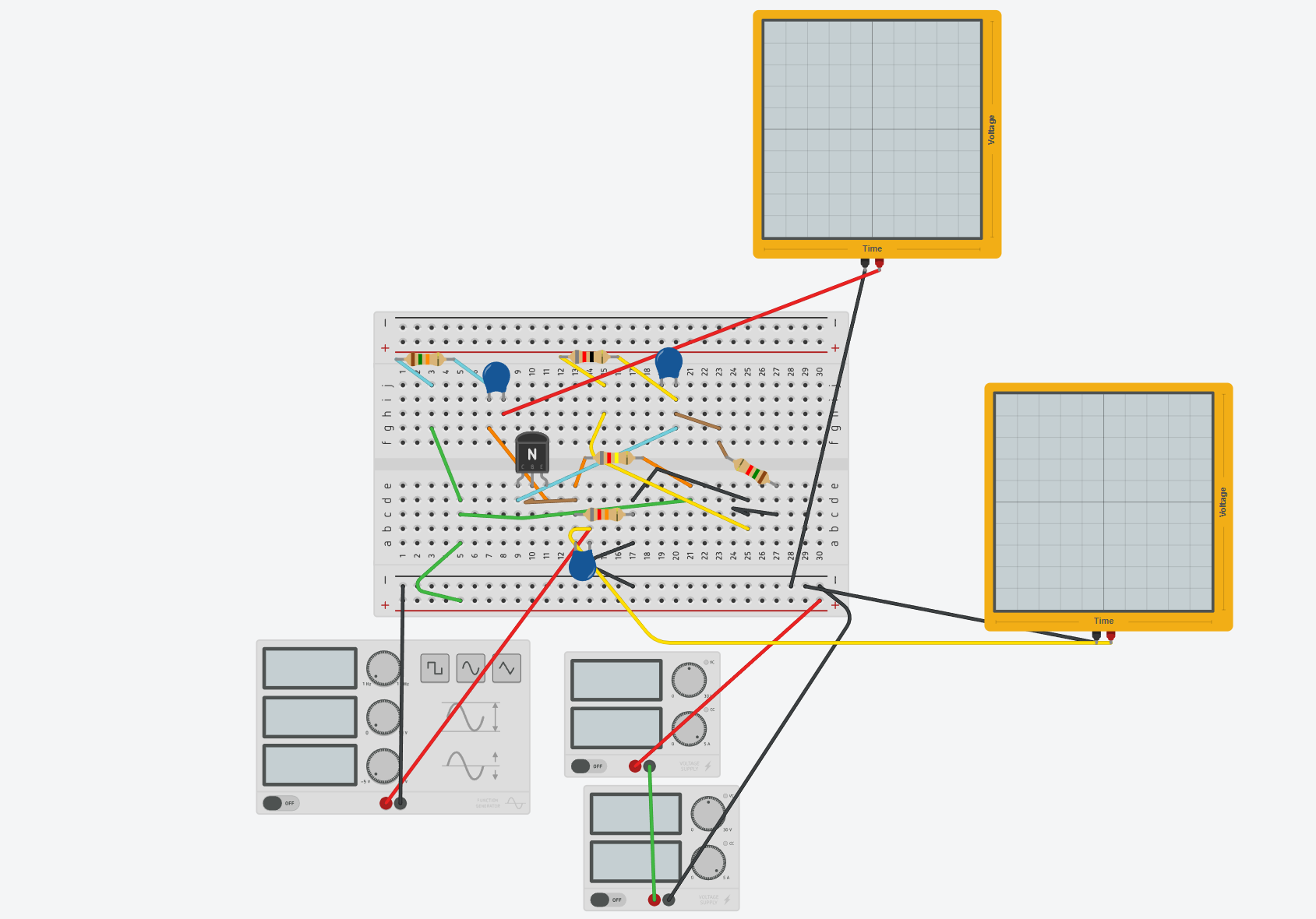
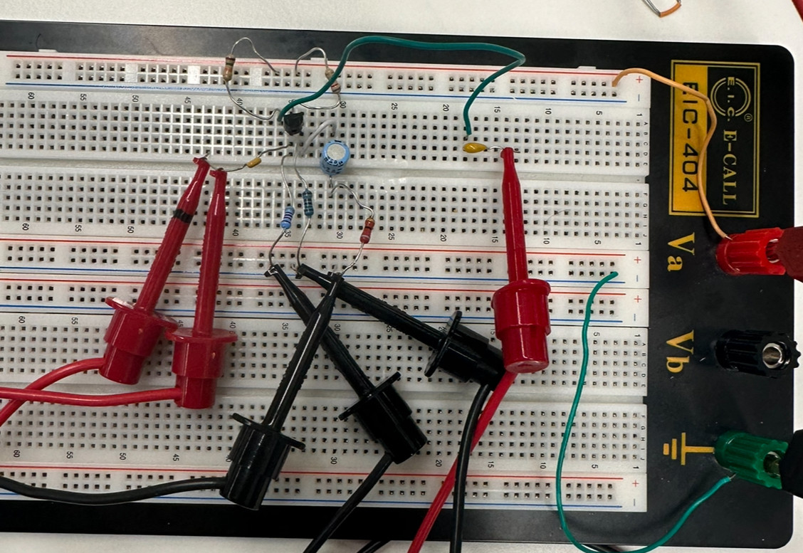
I am not sure what I am missing because it feels like I did something wrong. I replicated the breadboard in Tinkercad so that you have an idea of what it looks like.

P.S. Sorry, I know it is a messy one, I am a bit out of practice on breadboards.

enter image description here

enter image description here

enter image description here enter image description here enter image description here enter image description here

\$\endgroup\$
7
  • 1
    \$\begingroup\$ Your breadboard software shows C and E swapped from what it actually is for a 2N3904. Check the datasheet and use the pinouts there as a basis for your wiring. \$\endgroup\$
    – Ste Kulov
    Commented Feb 21 at 10:36
  • \$\begingroup\$ Thank you for the tip, yes I did correct in the software, but on the Breadboard it was correct. also I connected he other side of C to the emiter. I still dont get the but still my Ch1 isn't getting any better. \$\endgroup\$ Commented Feb 21 at 12:42
  • 1
    \$\begingroup\$ Try to remove C3 and Re’. It rapidly increases the gain so circuit works like switch, not an amp. \$\endgroup\$ Commented Feb 21 at 13:20
  • 1
    \$\begingroup\$ What is an "emitter circuit"? Do you mean "common-emitter circuit"? Note that "common-emitter circuit" doesn't mean "a common circuit" (although it is actually pretty common), it means something more like "a circuit in which the emitter is 'commoned' (aka grounded - sort-of)". \$\endgroup\$
    – brhans
    Commented Feb 21 at 13:21
  • \$\begingroup\$ Remove C3 and Re initially .|| Try a much lower frequency initially. Observe. \$\endgroup\$
    – Russell McMahon
    Commented Feb 21 at 13:25

2 Answers 2

1
\$\begingroup\$

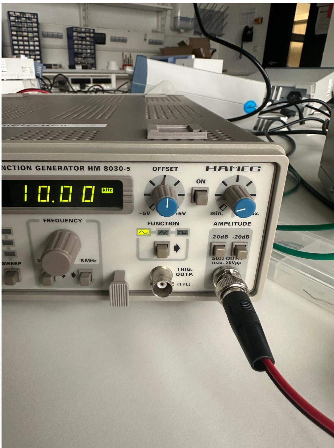
You show 0.1V input in the simulation, yet ~5V on the breadboard. The waveform appears to be normal operation for such heavy overdrive. You will observe shifts in bias voltages for the same reason.

Simply reducing the input voltage will get the expected result, and bias voltages should match within reason.

\$\endgroup\$
2
  • \$\begingroup\$ I have adjusted the Inputs Amplitude and I got a similar results, Thank you. Would you say that the replication from the simulation is accurate? \$\endgroup\$ Commented Feb 21 at 15:00
  • \$\begingroup\$ I would need to see more nodes' measurements and more detail to tell exact differences, but yes that looks much better. \$\endgroup\$ Commented Feb 21 at 15:38
0
\$\begingroup\$

Your amplifier seems to be working. The problem is that your output signal is too large. The output needs to be within the range of the supply voltage. The gain is ~180, which gives an output of +/-18V for a 0.1V input. You would probably need a 40V power supply to handle this output. Try removing Re', which will reduce the gain to ~10. You should see better agreement with simulation then.

\$\endgroup\$
11
  • \$\begingroup\$ I have removed Re, The Sin waves became more flat than round, and I adjusted the Amplitude through Function generator. but the end results is exactly the same as with it. So without the Re I have the Same image as above on the Oscilloscope \$\endgroup\$ Commented Feb 21 at 16:19
  • \$\begingroup\$ You removed Re', right? The 82-ohm resistor? \$\endgroup\$
    – Adam Haun
    Commented Feb 21 at 16:28
  • \$\begingroup\$ at first I made a mistake and removed the 1.5k but I just did the 8.2 ohm and still it looks the same. Is it normal that when I remove C the 100uF capacitor nothing changes? I even tried replacing it. Because I feel that could be the reason why when I remove the Re (82 Ohm) I get the same results as with ReI dont even need to change anything to the Function generator. I really appreciate the help \$\endgroup\$ Commented Feb 21 at 16:41
  • \$\begingroup\$ Removing the 100uF capacitor should mess up your DC bias. To be clear, is the yellow trace (channel 1) the output node? What do you see when you scope the collector voltage directly? \$\endgroup\$
    – Adam Haun
    Commented Feb 21 at 18:32
  • \$\begingroup\$ @BenMüller You just wrote above about removing the 8.2 ohm resistor. But your question shows 82, not 8.2. Which were you using, in reality? Details do matter. \$\endgroup\$ Commented Feb 21 at 21:36

Your Answer

By clicking “Post Your Answer”, you agree to our terms of service and acknowledge you have read our privacy policy.

Not the answer you're looking for? Browse other questions tagged or ask your own question.