0
\$\begingroup\$

Question

How do I troubleshoot the ESP32 USB JTAG/UART interface on a new PCB design?

Background

My son is working on a project to track satellites and this is the first time that we have worked with USB a layout, and the first time that we have put an ESP32-C6 module on a manufactured board. So far we have just used the ESP32 development kits and of course for those, USB JTAG works out of the box.

Schematics and layout are below.

This is what works on our board:

  • The debug UART we exposed on the board. (We can flash the program over the UART.)
  • USB +5 and the 3.3v LDO
  • The OLED driven over I2C by the ESP32C6

What doesn't work:

Even after flashing the default bootloader from an Espressif I2C OLED example program, the USB JTAG interface does not show up when we plug into a desktop USB host and watch dmesg -w.

We have already verified that there are no shorts between any of USB D+/-, GND, +5 or +3.3. The schematic was designed as nearly identical to the development kit's reference schematic.

... so, how do we go about troubleshooting the USB communication issue?

If there is a software setting that has to be enabled to activate the USB JTAG interface, then please point that out as well.

Thanks for your help!

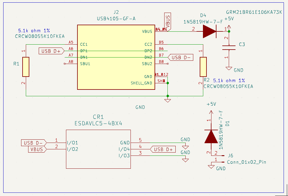
USB Connector Schematic

The bottom-left thing is an ESD suppressor:

USB Connector Schematic

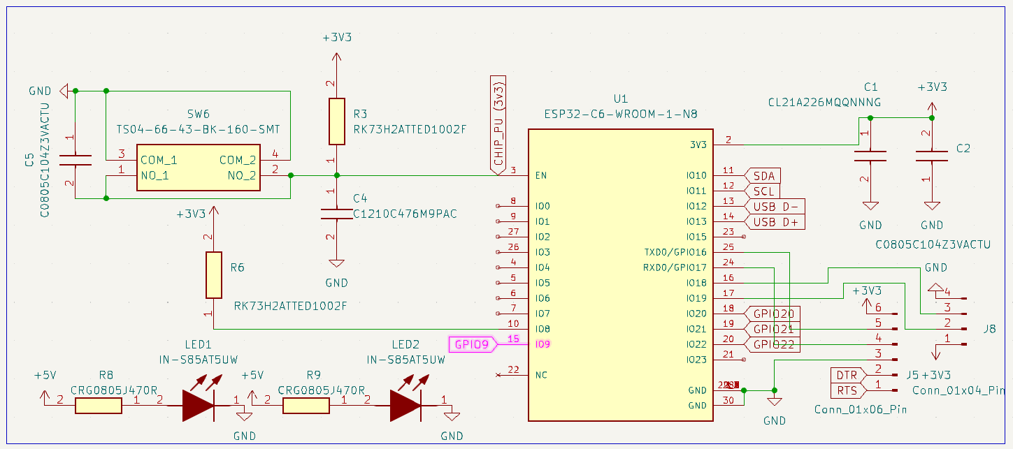
ESP32-C6 Schematic on our board

See netlabels between schematics

ESP32-C6 Schematic

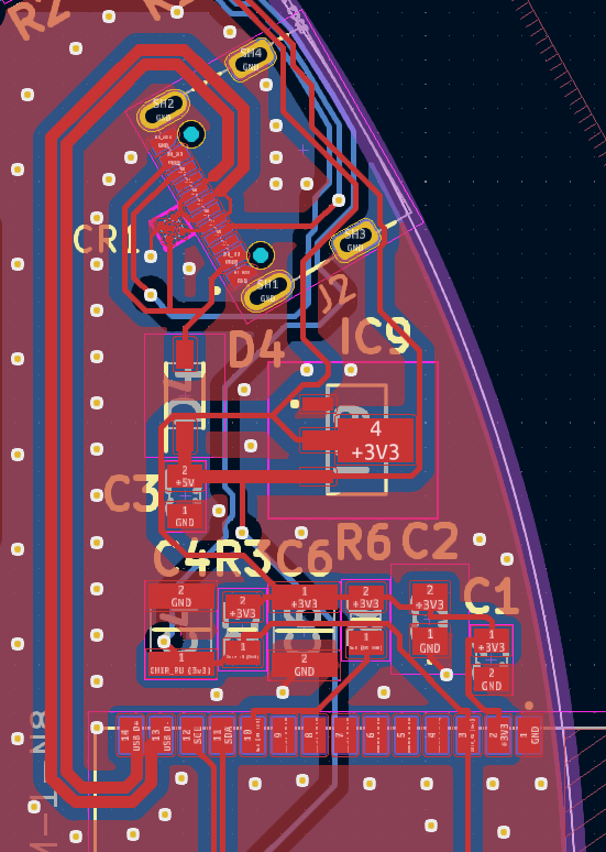
Our layout near the ESP32

We calculated a 90-ohm differential trace, which you can see in the layout quite clearly. Even if impedance is off slightly the traces extremely short so am surprised that we do not see any USB traffic at all.

ESP32 C6 USB layout

\$\endgroup\$

1 Answer 1

0
\$\begingroup\$

It turns out our D+ pin didn't have enough solder to the ESP32. In case it helps someone else, this is how we troubleshot the issue:

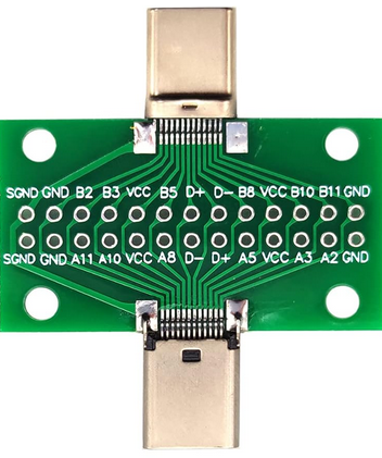
First, get a USB-C breakout passthrough board (passthrough is optional, but might be useful):

USB-C breakout

and then,

  1. Verify that none of D+, D-, VCC, and GND are shorted to any other.
  2. Verify that A5 to GND measures 5.1kOhm
  3. Verify that B5 to GND measures 5.1kOhm
  4. Verify that A5 to B5 measures 10.2kOhm
  5. Verify that D+ connects to ESP32's D+ (GPIO 14 on our board) by touching the pad on the base board's pad.
  6. Repeat #5 by touching the pad atop of the ESP32 module's castellated hole but not the base board's pad.
    • This is where we had our problem: #5 worked, but when we tested #6, there was a poor solder joint between the ESP32 module and the base board. We had originally tested by probing the crack between the board and castellated hole (which shorted both) and assumed that that D+ and D- were good...but the probe itself provided a false positive. When we measured the top of the ESP32 castellated hole pad, separately from the baseboard's pad, we found the broken connection.
  7. Repeat #5, and #6 for D- (GPIO 13 on our board)
  8. Fix any bad spots with a bit of heat and solder.
  9. DISCLAIMER: Test your device at your own risk: You are building a custom USB device, so if there is a problem with the port and you fry your USB host then that is your responsibility. That said, if you choose to proceed:
    • Remove the breakout board and test in Linux with dmesg -w and you should see something like this when you plug it in:
kernel: usb 3-2.4: new full-speed USB device number 59 using xhci_hcd
kernel: usb 3-2.4: New USB device found, idVendor=303a, idProduct=1001, bcdDevice= 1.02
kernel: usb 3-2.4: New USB device strings: Mfr=1, Product=2, SerialNumber=3
kernel: usb 3-2.4: Product: USB JTAG/serial debug unit
kernel: usb 3-2.4: Manufacturer: Espressif
kernel: usb 3-2.4: SerialNumber: 40:4C:CA:AA:BB:CC
kernel: cdc_acm 3-2.4:1.0: ttyACM3: USB ACM device
\$\endgroup\$

Your Answer

By clicking “Post Your Answer”, you agree to our terms of service and acknowledge you have read our privacy policy.

Not the answer you're looking for? Browse other questions tagged or ask your own question.