2
\$\begingroup\$

INTRODUCTION:

I've been having a hard time in class trying to understand phase angles. I understand a few concepts which I've stated below for clarity in regards to this discussion.

1.) Inductors-->Current LAGS Voltage by 90 degrees.

INDUCTOR FORMULA

I know that current through an inductor induces voltage which acts against current. Therefore, when voltage is at it's maxima or minima current is zero. This is clearly stated in the formula above when we set the slope (change in voltage respect to time) of the tangent line equal to zero.

2.) Capacitors-->Current LEADS Voltage by 90 degrees.

CAPACITOR FORMULA

I know that current doesn't travel through a conductor. The electric flux is exchanged "coupled" across the dialectic "insulator" as voltage builds up on one side of the plate. Therefore, when the change of current, respect to time, is at it's greatest voltage is zero.

QUESTIONS:

I cannot get my head around on how to intuitively understand phase angles and more importantly how to analyze a parallel section of a network.

Trying to understand/analyze what the phase angle is for each component as we move down a series/parallel circuit is just plain confusing. Can anyone help me out or provide some educating online resources that could help out? A resource that could help me understand and construct a phasor diagram would even be helpful also.

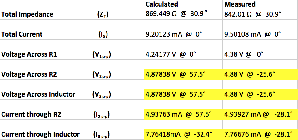
I have attached an image of a circuit I had to construct and measure the characteristics of in class this week. I am also attaching the table of which includes my calculations and measurements. In the table I highlighted where my phase angles are mixed up. If someone could explain why my phase angles are not lining up that would be a great help also.

My AC source is set to the following parameters.

8 Volts Peak to Peak

10kHz as Frequency
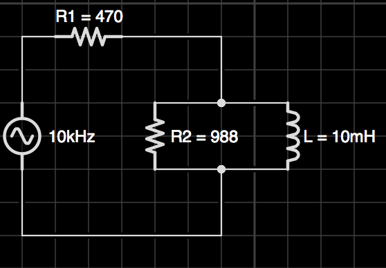
CIRCUIT

TABLE

\$\endgroup\$
1
  • \$\begingroup\$ I think you've got your inductor and capacitor pictures in your question mixed up. Also when you said "current doesn't travel through a conductor" you meant "insulator". \$\endgroup\$
    – Andy aka
    Commented May 24, 2013 at 19:14

2 Answers 2

1
\$\begingroup\$

The easiest way of solving such problems is to use complex phasors. The total complex impedance is

$$Z_T=R_1+R_2||j\omega L=R_1+\frac{j\omega R_2L}{R_2+j\omega L}=877.18\cdot e^{30.67^{\circ}}\Omega$$

with \$\omega=2\pi\cdot 10,000 Hz\$, \$R_1=470\Omega\$, \$R_2=988\Omega\$, and \$L=10mH\$ (as shown in your circuit diagram).

This gives for the total current

$$I_s=\frac{V_0}{Z_T}=9.12\cdot e^{-30.67^{\circ}} mA$$ with \$V_0=8V\$.

The voltage across \$R_1\$ is

$$V_1=I_sR_1=4.28\cdot e^{-30.67^{\circ}} V$$

The voltage across \$R_2\$ and \$L\$ is

$$V_2=I_s(R_2||j\omega L)=I_s\frac{j\omega R_2L}{R_2+j\omega L}=4.83\cdot e^{26.88^{\circ}} V\quad(=V_0-V_1)$$

The current through \$R_2\$ is

$$I_2=\frac{V_2}{R_2}=4.89\cdot e^{26.88^{\circ}} mA$$

The current through the inductor is

$$I_L=\frac{V_2}{j\omega L}=7.70\cdot e^{-63.12^{\circ}} mA\quad(=I_s-I_2)$$

I realize that there are quite a few differences between these results and your calculations and measurements. I just used the values you gave in the circuit diagram, and I did my best to avoid any errors.

\$\endgroup\$
0
\$\begingroup\$

Do you know about the Smith chart? Specifically I'd recommend this tutorial. I wish I could put more directly in the answer, but the great thing about that tutorial is its interactivity, and seeing how reactive components relate to the chart.

\$\endgroup\$

Not the answer you're looking for? Browse other questions tagged or ask your own question.