0
\$\begingroup\$

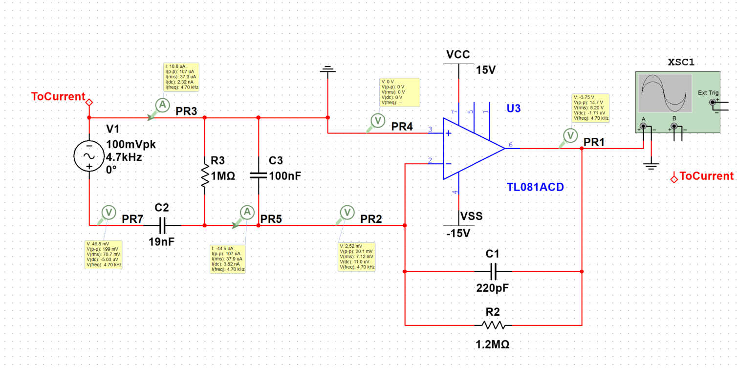
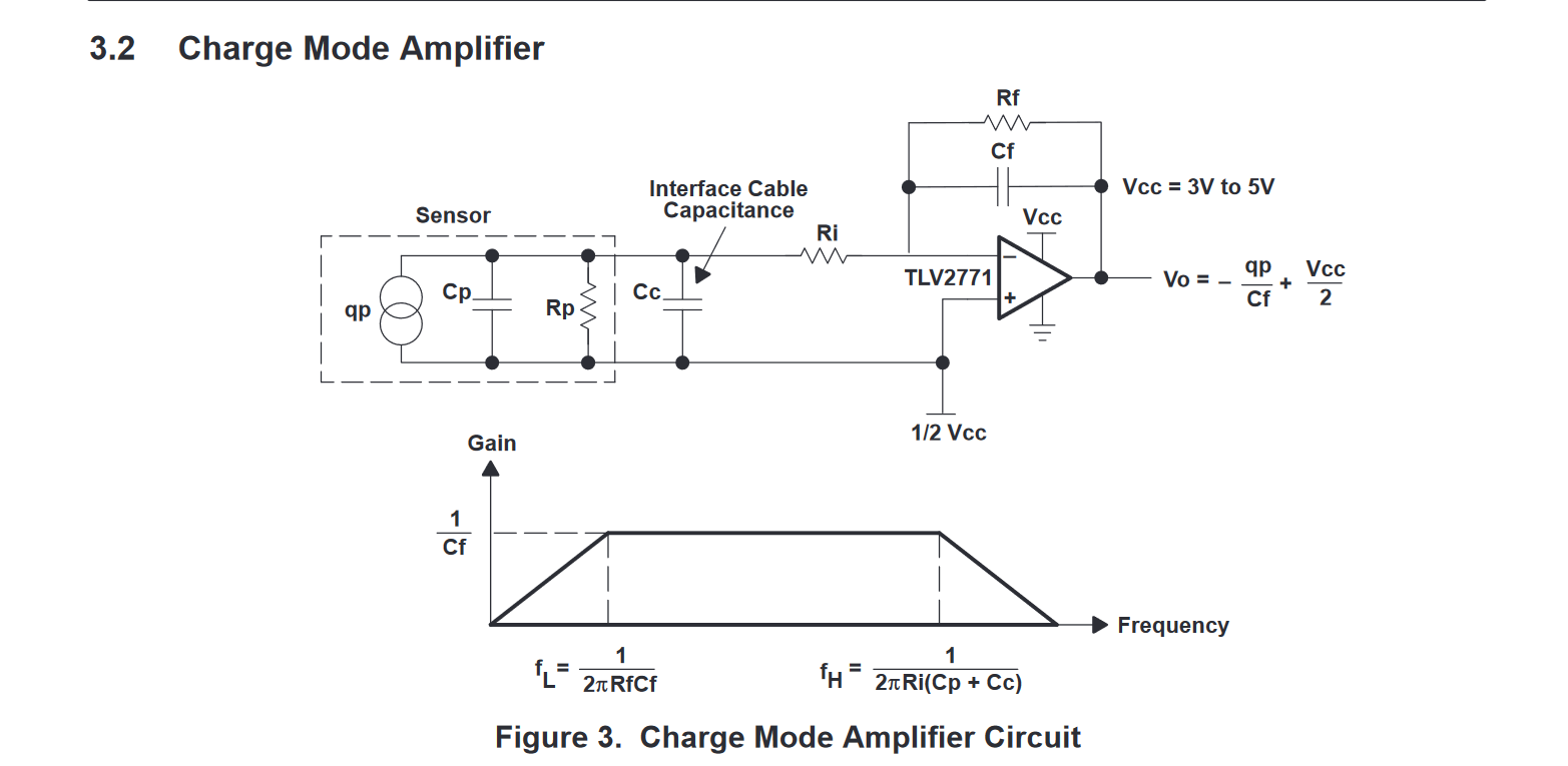
I have a piezoelectric element, which acts as an accelerometer. Attached to it is a charge amplifier, built based on this documentation. The op-amp is the TL081.

enter image description here

The PZT element is simulated based on a model, where C2 is the transducer capacitance, R3 is the leakage resistance, and C3 is the stray capacitance.

Per my understanding, the charge amplifier should provide a "gain" of -C2/C1, as Vo = -Qp/Cf, and Qp is correlated to the transducer capacitance C2. I am producing an AC signal with offset of 0V, so I will simplify this gain to C2/C1.

enter image description here

My issue is that the charge amplifier does not amplify on most lower frequencies. According to my understanding, the cutoff frequency should be (22010^-121.210^62pi)^-1 = 602Hz. However, I am experiencing no amplification until at least 3.5kHz. The peak is still 6kHz.

This is currently being built on an op-amp.

Things I've tried:

  • Swapping the Op-amp. No effect.
  • Changing the PZT element into a sine wave generator to simulate the sine wave. No effect.
  • Swapping the parts to confirm the value of the resistor/capacitor 220pF and 1.2MOhm. No change.

Please let me know if more information is required.

\$\endgroup\$
1
  • 1
    \$\begingroup\$ C3 is much, much too large. Stray capacitance should only be tens to hundreds of pico-Farads. \$\endgroup\$ Commented Mar 4 at 2:23

1 Answer 1

2
\$\begingroup\$

Your value for C3 is way too large. It is the main reason that signals at most frequencies are being attenuated. It is only when the impedances of C2 and C3 become comparable, that fluctuations can begin to appear at their junction. That condition only occurs at high frequency.

C3 is supposed to represent the combined parasitic capacitance of elements such as op-amp inputs and cabling. For instance:

  • The TL081's inputs will have a couple of picofarads between them.

  • 1m of twisted wire pair used to connect the transducer will have something like 50pF capacitance between the conductors.

  • PCB traces will add a few more picofarads

At a guess, I would expect C3 to be anywhere between 20pF and 200pF, not 100nF.

\$\endgroup\$
1
  • \$\begingroup\$ Thank you. Are there any suggested reading on the combined parasitic capacitance? \$\endgroup\$ Commented Mar 13 at 17:51

Your Answer

By clicking “Post Your Answer”, you agree to our terms of service and acknowledge you have read our privacy policy.

Not the answer you're looking for? Browse other questions tagged or ask your own question.