8
\$\begingroup\$

I was making a circuit with 1 LED and 1 transistor. pretty primarily i was trying to use the transistor as a normal switch. Here is the diagram below.
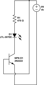
enter image description here

So, this is an NPN transistor and i connected the -ve part of the D1 (transistor) with the -ve part of the LED and the other -ve leg of D1 to ground. I connected the +ve part of D1 with the positive end of 9V dc power supply. The LED should light up and if I disconnect the wire connecting the +ve part of D1 , the LED should turn off. But the problem that I am facing is that the LED isn't lighting up when I connect all the points and follow the schematic.

Also another problem that I am facing is that when I connect a wire with the +ve leg of D1 and don't connect the other end of the wire with the battery and just hold the wire by my fingers, the LED turns on but emits very little light. Is there any mistake in my schematic?

\$\endgroup\$
0

2 Answers 2

22
\$\begingroup\$

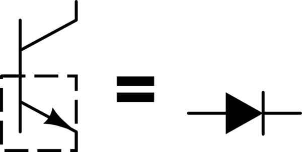
The base-emitter junction of a bipolar junction transistor is a diode:

schematic

simulate this circuit – Schematic created using CircuitLab

You have another diode in your circuit, the LED. And you obviously understand that you need a current-limiting resistor if you want to connect this diode to a 9V battery, because a diode has an approximately constant voltage drop that is less than your battery voltage.

The problem is the same with the transistor in your circuit. You have the base connected to the positive side of your battery, and the emitter connected to the negative side. You've done this, essentially:

schematic

simulate this circuit

What will happen here? A whole lot of current will flow until the battery can supply no more, or something melts. If you are using a 9V battery, it can't supply a whole lot of current, and I bet if you measure the battery voltage in your circuit, it's about 0.65V, unless the battery is dead by now.

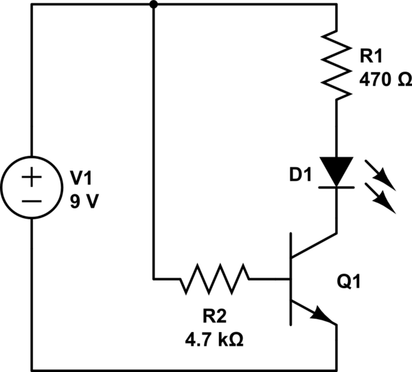
So what you need is a current-limiting resistor on the base of the transistor, like this:

schematic

simulate this circuit

After you understand that, you might read Why would one drive LEDs with a common emitter?

\$\endgroup\$
1
  • 3
    \$\begingroup\$ Good answer, especially on the battery and diode part. \$\endgroup\$
    – jippie
    Commented May 25, 2013 at 13:05
20
\$\begingroup\$

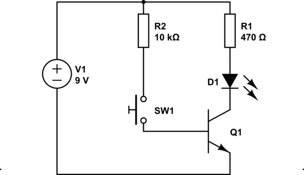
Change your circuit to look like this:

schematic

simulate this circuit – Schematic created using CircuitLab

In your circuit you connect base to +9V and emitter to 0V, that is not good and may kill the transistor. A BJT (bipolar junction transistor) as drawn is current driven: you need a small base current to make it conduct a large current from collector to emitter. The base-to-emitter voltage should never be higher than 0.6~0.7V or so and that is where my R2 comes in.

So base voltage is given: approximately 0.7V. The base current can be calculated as follows:

\$I_B = \dfrac{U_{R2}}{R2}= \dfrac{9\text{V}-0.7\text{V}}{10\text{k}\Omega}\approx0.8\text{mA}\$

The collector current is limited by R1 and D1 if the transistor is saturated. Saturated means there is almost no voltage across collector and emitter.

\$I_C= \dfrac{V1-V_{D1}}{R1} = \dfrac{9-1.8\text{V}}{470\Omega}\approx 15\text{mA}\$

So the current minimum current gain you want from your transistor is:

\$h_{FE} = \dfrac{I_C}{I_B}=\dfrac{15\text{mA}}{0.8\text{mA}} \approx 20\$

If you look at the datasheet for your 2N2222 and look up the hFE-parameter you'll find it is much larger than 20 (minimum 75 according to the datasheet) therefore the transistor will suffice. You can even consider increasing R2 to about 33kΩ and it should still work just fine.

\$\endgroup\$
4
  • \$\begingroup\$ Understood. ok I am making the circuit. Lets see what happens. Thank you! \$\endgroup\$ Commented May 25, 2013 at 12:51
  • \$\begingroup\$ By the way. The switch that you are using, is that a momentary tact switch> or push button switch? \$\endgroup\$ Commented May 25, 2013 at 12:52
  • \$\begingroup\$ I drew a push button momentary switch, but you can replace it with any switch you want. Even two wires that you hold together will do just fine. \$\endgroup\$
    – jippie
    Commented May 25, 2013 at 13:04
  • \$\begingroup\$ Ok . Thanks. I also have tact switch and its working perfectly \$\endgroup\$ Commented May 25, 2013 at 13:06

Your Answer

By clicking “Post Your Answer”, you agree to our terms of service and acknowledge you have read our privacy policy.

Not the answer you're looking for? Browse other questions tagged or ask your own question.