0
\$\begingroup\$

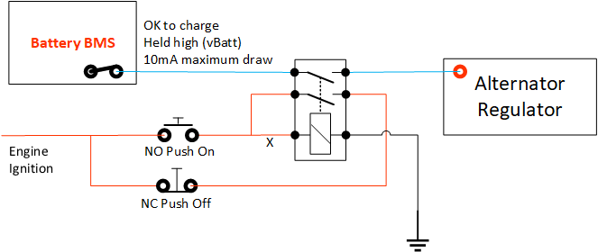
I have the following circuit for controlling an engine alternator regulator.

enter image description here

When the regulator sees vBatt on it's input it enables a specific CC/CV charging profile.

I have designed a, (untested), circuit, (which I hope is right), to turn the charge signal on/off and also have it default to off when the engine ignition is turned off.

What I would like to do is integrate the blue circuit into the logic. If the blue circuit is switched off/goes open circuit, by the BMS then I would like the relay to also switch off. This will require the user to consciously enable charging after a BMS disconnect, rather than have it automatically restart if the BMS decides charging is OK.

I believe that I am looking for a component that I can insert at position X which is controlled by the blue circuit. As the output is only 10mA I can't use a standard relay, which would not be ideal anyway, due to excessive power draw from the coil.

Ideally also, the relay should not be able to be engaged if the BMS output is open circuit.

Thanks

Notes: All systems have a common ground reference. vBatt and vIgnition is 9 - 15v

\$\endgroup\$

1 Answer 1

1
\$\begingroup\$

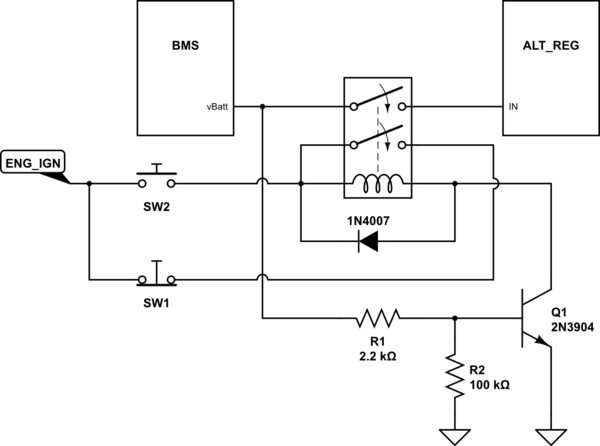
You could use an an NPN transistor in the ground lead to the relay, emitter to ground, collector to relay coil, base to vBatt through a resistor and a resistor from base to ground to ensure turnoff. As long as vBatt is high the transistor is on and the relay can operate, when vBatt is low the transistor is cut off and the relay won’t operate. You could use a MOSFET as an alternative, and you should add a diode across the coil for transient protection.

It should look something like this:

schematic

simulate this circuit – Schematic created using CircuitLab

\$\endgroup\$
2
  • \$\begingroup\$ Wow - thank you so much. Do you feel that this is "automotive safe" - the ENG_IGN is currently sourced direct from a battery via a ignition_relay. That relay is triggered by the engines CANBUS power/on. Are there better components I could use to make it automotive safe, or should I consider sourcing this ENG_IGN also from the engine CANBUS power to be safe? \$\endgroup\$ Commented Mar 5 at 21:47
  • \$\begingroup\$ @RowanSmith This is just to give you a basic idea of how you could do it by switching the relay ground, You'd have to fit it to your particular use case such as by adding transient protection. I just used a generic transistor, you'd need to use something capable of handling the relay current and maybe one specified for automotive use. \$\endgroup\$
    – GodJihyo
    Commented Mar 5 at 22:29

Your Answer

By clicking “Post Your Answer”, you agree to our terms of service and acknowledge you have read our privacy policy.

Not the answer you're looking for? Browse other questions tagged or ask your own question.