I'm talking about a simple circuit - source, resistor and LED in series.
I've seen many examples of how to calculate the resistor value based on source voltage and the desired current and voltage of the LED.
But if you only know the source voltage and the resistor value, how can you calculate the current through the circuit and the voltage across the LED?
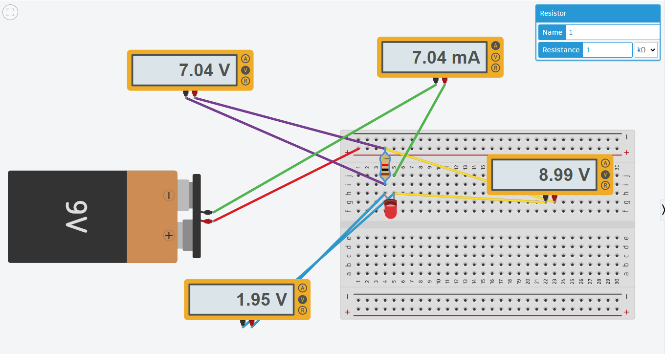
I tried to simulate this on tinkercad by linking a 9V battery with a 1 kOhm resistor and a LED, and got these values:
 However, I cannot figure out how the simulator came up with them. I guess it just assumed that the red LED will have the typical forward voltage of 1.95V, and then the rest of the values come naturally (resistor's voltage = 9 - 1.95 = 7.05, so current is 7.05/1000 = 7.05 mA).
But if so, my question is - how is that assumption justified? To me, it seems quite arbitrary.
-
\$\begingroup\$ You cannot solve for two unknowns with a single equation, that's algebra. You need to look up the forward voltage for your LED or else set the other unknown (current )to a value you do know and measure it for your specific device. Asking a simulator to guess the forward voltage of an unknown component is nonsense. \$\endgroup\$– user1850479Commented Mar 13 at 2:34
-
\$\begingroup\$ The voltage of an LED is related to the amount of energy that goes into each photon of light that comes out. It's not just a random number. \$\endgroup\$– Criticizing Israel not allowedCommented Mar 13 at 2:42
4 Answers
The old fashioned way (without simulator) to do it relatively accurately is to draw a "load line" on the LED curve.
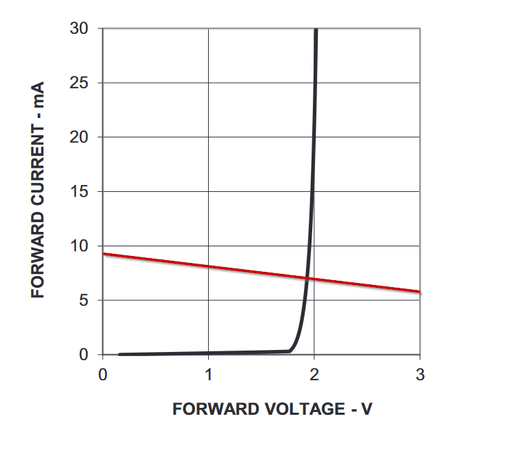
Here is a curve taken from this datasheet, on which I've drawn a straight red line. It's straight because resistors are linear. LEDs are not.
Where the load line crosses the Y axis represents the current through the resistor if the LED voltage was 0V (it would be 9V/1kΩ = 9mA). Where it crosses the 3V vertical line is the current if the LED voltage was 3V (6V/1kΩ = 6mA).
Where the two lines cross is where the actual current and voltage will be. In this case, with this LED, a 1kΩ resistor and a 9.0V supply, it will be about 7.1mA and the LED voltage will be around 1.93V.
As you can see, though, for currents that are 5mA+ the LED voltage will be somewhere between 1.9V and 2V so if we use 1.95 we'll get an answer that's good enough for most purposes in that range. After all, as the battery dies the voltage will change considerably. If you use the fixed voltage to predict the LED current (and therefore the brightness) as the battery voltage drops you'll get an overly pessimistic answer- in fact the LED forward voltage will drop as the battery dies, the current draining the battery will drop, and it will emit a weak light far longer that you'd predict using the fixed voltage approximation. This particular LED is a red LED. Generally shorter wavelength LEDs such as green, yellow and blue have higher forward voltages (2 or 3V typically) at similar currents and longer wavelength types such as the IR LEDs used in remote controls and optocouplers have lower forward voltages (a bit over a volt). Colors like pink and white generally use blue dies and some phosphor so they behave electrically like blue LEDs.
SPICE based simulators have a nonlinear equation (similar to the Shockley equation with some enhancements such as a resistive component) that represents the above curve (potentially quite accurately if the model parameters are good) and they solve this equation numerically, iterating to a precision that is better than the models generally. Different models of LED (even of the same color and chemistry) will have different parameters depending on many factors. Many closed-source circuit simulators (of which I assume Tinkercad circuits is one) are based on SPICE, originally developed as an open-source project at Berkeley in the 1970s- with even earlier military origins.
Here is what a typical set of diode model parameters looks like, for an SMT Kingbright 0603 red LED:
.model APT1608SURCK d(IS=2.01E-17 N=2.139 RS=2 m=0.431 Vj=2.32 Cjo=35pF IBV=10u BV=5 EG=2.26 XTI=3 Iave=30mA Vpk=5 mfg=Kingbright type=LED)
As you can see there are quite a few numbers associated with the LED and nowhere is the Vf explicitly stated. If you really want to go down a rabbit hole, the actual model is explained here.
Cleaner copy with additional information here, pp49-71, courtesy of @periblepsis.
-
\$\begingroup\$ A much cleaner scan with that chapter in full context can be found here. \$\endgroup\$ Commented Mar 13 at 5:53
-
\$\begingroup\$ @periblepsis Thanks, I've edited it in. Left both because the cruddy copy might have more longevity, being on a wiki. \$\endgroup\$ Commented Mar 13 at 6:03
-
1\$\begingroup\$ Hmm. Good idea. Apparently originally from Motorola as "Rectifier Applications Handbook," HB214/D, ©1993, ISBN 0−929270−00−2. Supposedly available from OnSemi now, by request. I should ask a local FAE and see what happens. \$\endgroup\$ Commented Mar 13 at 6:42
-
\$\begingroup\$ Thank you, that's a very ingenious way to visualize the solution, and it makes the most sense to me! \$\endgroup\$ Commented Mar 18 at 0:46
You've got a number of resonances by others on your question. But I'll dive directly in to demonstrate that it's not an assumption by Tinker.
The Shockley diode model can be simplified for these purposes to the following:
$$I_\text{D}=I_\text{SAT}\cdot\left[\exp\left(\frac{V_\text{D}-R_\text{D}\cdot I_\text{D}}{\eta\,V_T}\right)-1\right]$$
Solving that for \$I_\text{D}\$ would take a page's worth of math steps, which I'll avoid. (Uses branch-0 of LambertW function, which gives \$u\$ for \$y=u\, e^u\$ when you know \$y\$.)
But it can be rewritten in this more easily reckoned with equation:
$$V_\text{D}=I_\text{D}\cdot R_\text{D}+\eta\, V_T\cdot \ln\left(1+\frac{I_\text{D}}{I_\text{SAT}}\right)$$
Apparently, Tinker uses \$\eta=1.75\$, \$R_\text{D}=6\:\Omega\$, and \$I_\text{SAT}=4\times 10^{-21}\$ for its RED LED diode model. And \$V_T=26\:\text{mV}\$ for its thermal voltage.
In your case, with \$1\:\text{k}\Omega\$, you got \$7.04\:\text{mA}\$. So:
(6*x+1.75*.026*ln(1+x/4e-21)).subs(x,7.04e-3)
1.95377896947390
And yes, that matches what the voltmeter shows for the RED LED voltage.
Let's try with \$2\:\text{k}\Omega\$ and get \$3.55\:\text{mA}\$ and find:
(6*x+1.75*.026*ln(1+x/4e-21)).subs(x,3.55e-3)
1.90168691368984
And yes again, that's what I got from Tinker for the LED voltage.
Let's up the current a bit so that \$R_\text{D}\$ matters more. Try with \$150\:\Omega\$ and get \$44.5\:\text{mA}\$:
(6*x+1.75*.026*ln(1+x/4e-21)).subs(x,44.5e-3)
2.26243555583850
And that's also what I get from Tinker for the LED voltage.
Tinker uses the Shockley diode equation to solve these problems. So it doesn't need to guess. It uses a model and the model behaves in a certain way.
But Spice programs are really fast and good at bookkeeping and numerical solving methods, where we humans are rather poor and slow at both of those. So Spice programs use what they are good at.
We humans find other ways.
-
1\$\begingroup\$ Very interesting, thank you for shining a light on the exact equation and the math behind the values displayed by Tinker! \$\endgroup\$ Commented Mar 18 at 0:49
-
1\$\begingroup\$ @CatalinFlorea No problem. Glad you found it interesting to see and thanks so much for letting me know so. I appreciate you taking a moment. Someday, if you have any interest in math for its own right, you might try and solve that first equation for \$I_\text{D}\$. It's an interesting exercise. \$\endgroup\$ Commented Mar 18 at 2:04
LED colors are - for the most part - set by the materials used to make them. Most LED colors have just one "recipe" or very similar recipes so the voltages will be similar. It's not precise; the closest you can get for an unknown LED is a pretty good guess. You can certainly hook it up to a current source and dial it up until you hit 10mA or 20mA or whatever the rated current is but if you know that, then you probably would know the Vf as well.
As for current, that kind of depends on how much light is being emitted. A SMD indicator light may pass just a few mA while a LED intended for outdoor lighting might be over an amp. Of course, the best thing is to check the datasheet for the device you have.
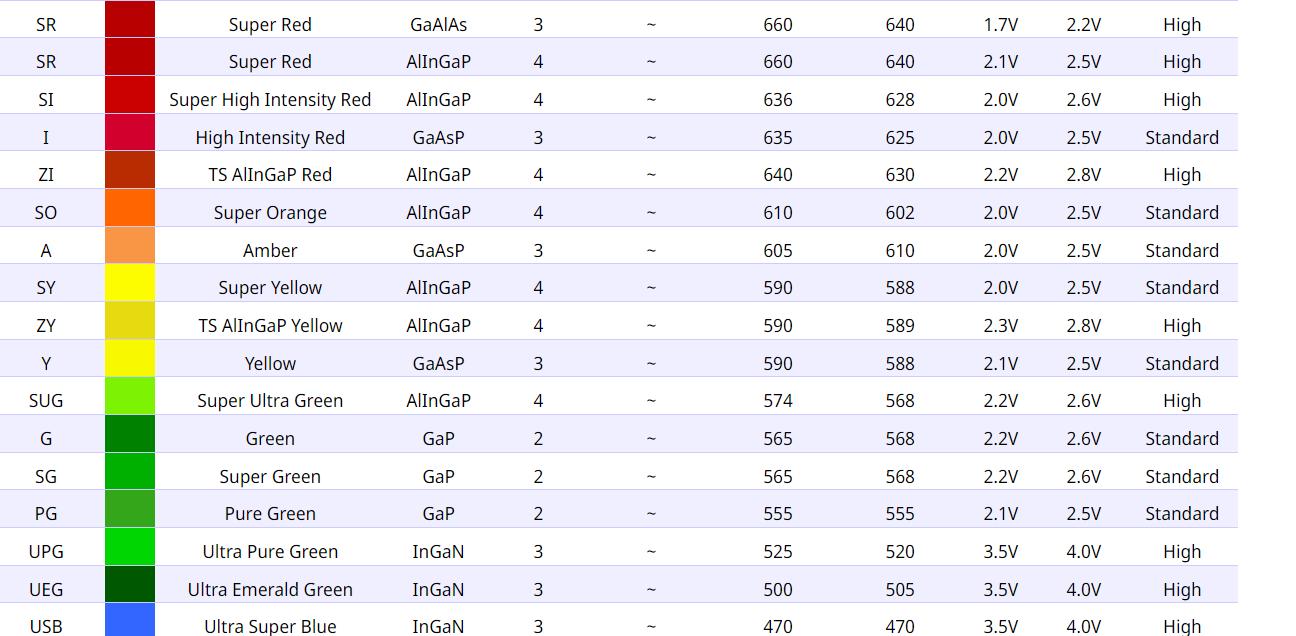
Lumex has a nice chart correlating colour to forward voltage. The actual voltage varies from device to device and manufacturer to manufacturer, so resistor selection must be based on worst case values.
However, I cannot figure out how the simulator came up with them.
If the part number is known to the simulator, then the forward voltage is known. Tinkercad may have a few preselected values that it chooses from. Anyway, the forward voltage of the LED must be known to calculate the current through the resistor.


