1
\$\begingroup\$

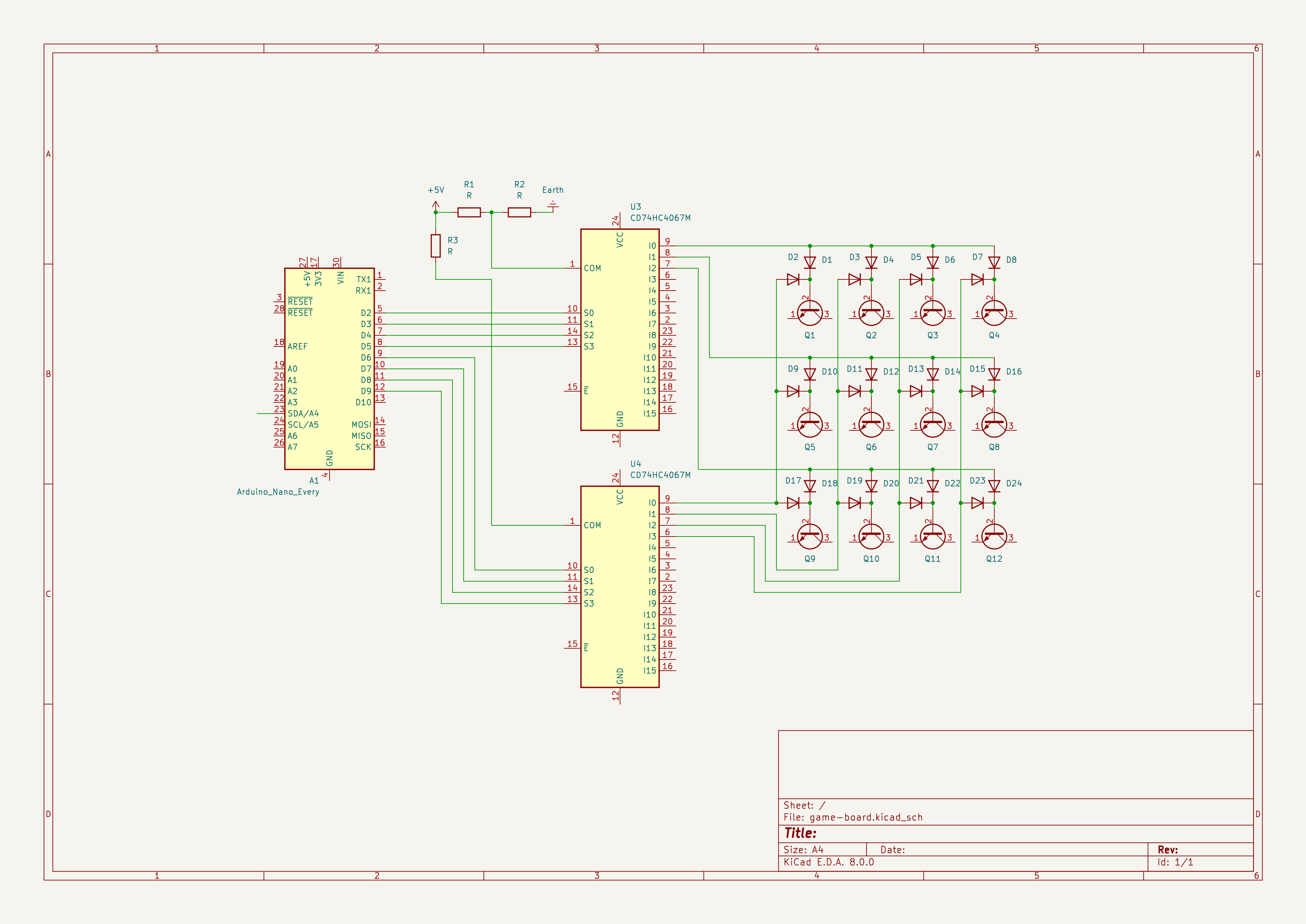
I have a specific application where I need to interface 256 i2c busses arranged in array of 16x16. I have used multiplexers to create LED arrays, but this problem seems different as there isn't part of the circuit to pull to ground as one would for LED's. If I had to only "write" to bus then it could be achieved with array of diodes, but I need to also read from the bus. I started to sketch something using transistors, but my hobby level knowledge was not enough to figure this one out. Best solution I could come up is adding currents from both muxers to trigger the transistor.

enter image description here

This is my best idea so far. Using a voltage divider thru both muxes to break thru mosfets threashold:

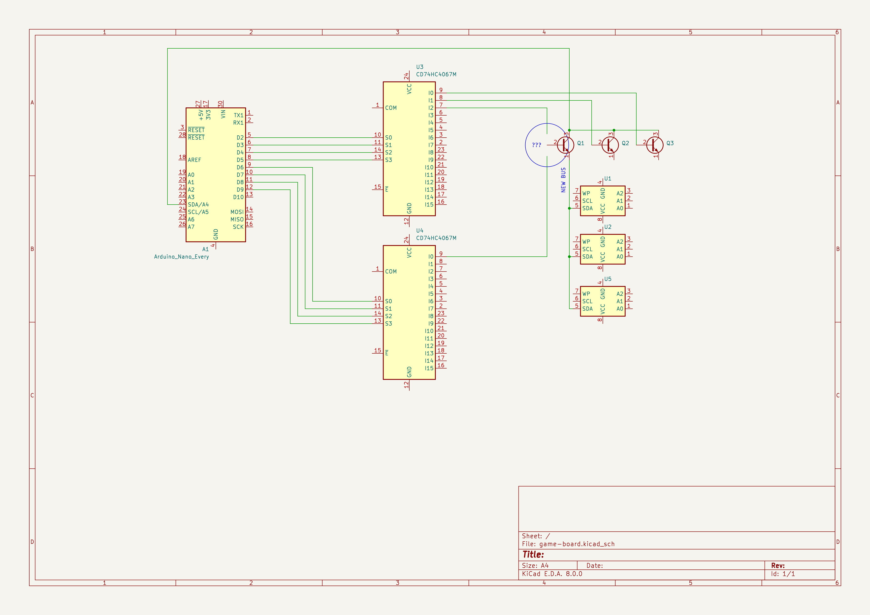
enter image description here

\$\endgroup\$
4
  • \$\begingroup\$ Since both I2C lines are bidirectional, the language can get messy. Let's define the matrix as having 16 X ports and 16 Y ports, and one crosspoint node as a pair of bidirectional connections (one for SCL and one for SDA). How many nodes will be connected simultaneously? IOW, if X3 is connected to Y7, can X3 also be connected to Y13? \$\endgroup\$
    – AnalogKid
    Commented Mar 13 at 12:37
  • \$\begingroup\$ No the array looks just like it would for a regular LED panel. So only one cross point would be active at any given time. \$\endgroup\$ Commented Mar 13 at 12:43
  • \$\begingroup\$ So, just to be clear, only one connection out of 256 is "on" at a time? \$\endgroup\$
    – AnalogKid
    Commented Mar 13 at 18:31
  • \$\begingroup\$ @AnalogKid exactly. \$\endgroup\$ Commented Mar 13 at 22:06

2 Answers 2

3
\$\begingroup\$

An I2C device only operates when it sees activity on both the clock and data lines. If it sees activity on only one or the other, the device will ignore the cycle.

So the obvious way to "matrix" a whole lot of I2C devices would be to connect SDA from the MCU to the COM input of your U3, and connect U3's outputs to the columns of your matrix. This goes directly to the SDA pins of the I2C devices in each column.

Similarly, connect the SCL from the MCU to the COM input of U4 and connect U4's outputs to the rows of your matrix. This goes directly to the SCL pins of the devices in each row.

In addition, each column and each row needs its own pullup resistor.

The one device in the matrix which receives both SDA and SCL will execute the current cycle. All other devices in the same column will see the SDA pin wiggling, but since their SCL pins are not moving, they just see a bunch of "start" and "stop" conditions that mean nothing to them. Similarly, all other devices in the same row see the SCL pin wiggling, but since they don't see the "start" and "stop" conditions on their SDA pins, they ignore the clock cycles too.

\$\endgroup\$
2
  • 1
    \$\begingroup\$ Oh wow. I never considered what happens when one or the other piece is missing. This really sounds like the best solution. I won't need any additional parts in the matrix, just the multiplexers! Thank you! Will try to build it and scope it out as soon as I get the i2c microcontrollers. \$\endgroup\$ Commented Mar 13 at 12:23
  • \$\begingroup\$ That's clever as heck. \$\endgroup\$ Commented Mar 13 at 15:48
0
\$\begingroup\$

A use case for multiplexer ICs. You can build this out of discrete transistors, it's called a transmission gate, but at this scale that is not only more expensive but also so complex and thus error-prone that I don't think you'd be well-advised to try.

So, simply buy the necessary amount of multiplexer ICs. Here's a list of candidates: https://www.digikey.com.au/short/0hnzr9qz

\$\endgroup\$
1
  • \$\begingroup\$ As you can see in my schematic I already have multiplex IC. My question was how to connect it in array setup so I could address 16x16 array of i2c busses. \$\endgroup\$ Commented Mar 13 at 11:51

Your Answer

By clicking “Post Your Answer”, you agree to our terms of service and acknowledge you have read our privacy policy.

Not the answer you're looking for? Browse other questions tagged or ask your own question.