First you need to know what the ripple current is.
The chip multiplexes the display: it turns on the rows of LEDs one at a time. So maximum ripple current would occur with a full dark row (zero current) followed by a full bright white row (48 x 20mA = 960mA).
If you're using separate supplies for RGB, that's 320mA per color. So for each supply, it can draw up to 320mA for a full bright row, then 0mA for a full dark row, then repeat.
If you're not using 20mA LED current then you can scale accordingly.
Frequency is not easily extracted from the datasheet, it is also configurable, but for a good visual aspect without flicker it should be pretty high. They mention about 3kHz max refresh rate, so with 16 rows each will stay lit for 20µs, which gives a ripple frequency from 24kHz (pattern of alternating bright and dark rows) down to a few kHz (top half rows bright, bottom half rows dark).
They require 5% voltage ripple on the supply, which means it should have an impedance below 3V * 5% / 320mA = 0.4 ohms in this frequency range. Say up to 50-100kHz for extra safety margin.
So you need to design your power supply to meet this required impedance. You'll probably be using buck converter(s) for the three supplies, and these have pretty low impedance at low frequency thanks to feedback. But at higher frequency this is no longer the case and the output caps are relied upon to provide low impedance.
10µF provides 0.4 ohms impedance above 50kHz. Below that it would rely on the buck converter's output impedance. So one will probably not get away with just one cap.
It's impossible to answer without knowing the output impedance of your buck converter, but... you get the idea: you should use enough capacitance to keep power supply impedance below what is required to get 5% ripple (at your LED current) in the desired range of frequency. Since you'll probably use several 10µF MLCC, high frequency should not be a problem. Low frequency (few kHz) should be taken care of by the buck converter, but you have to be careful not to have an impedance peak between the two. This is why they recommend electrolytic caps.
If you want less caps, then you need a buck that runs at high frequency, with a control scheme that ensures quick transient response, which is the time domain equivalent of "low output impedance up to higher frequency".
I can't use the recommended electrolytic due to the leakage
I have no idea what you mean by this, modern electrolytics have extremely low leakage current. However the board will probably get quite hot due to all these LEDs, so it would be a good idea to use 105°C low-ESR caps. I think 100-300µF should work well, but again it all depends on the characteristics of your buck converter.
If you use several 16x16 LED blocks powered from one supply you should also consider the maximum output capacitance the buck converter will tolerate, and/or perhaps tune the soft-start to make sure it does not freak out and go into short circuit protection mode due to the huge inrush current.
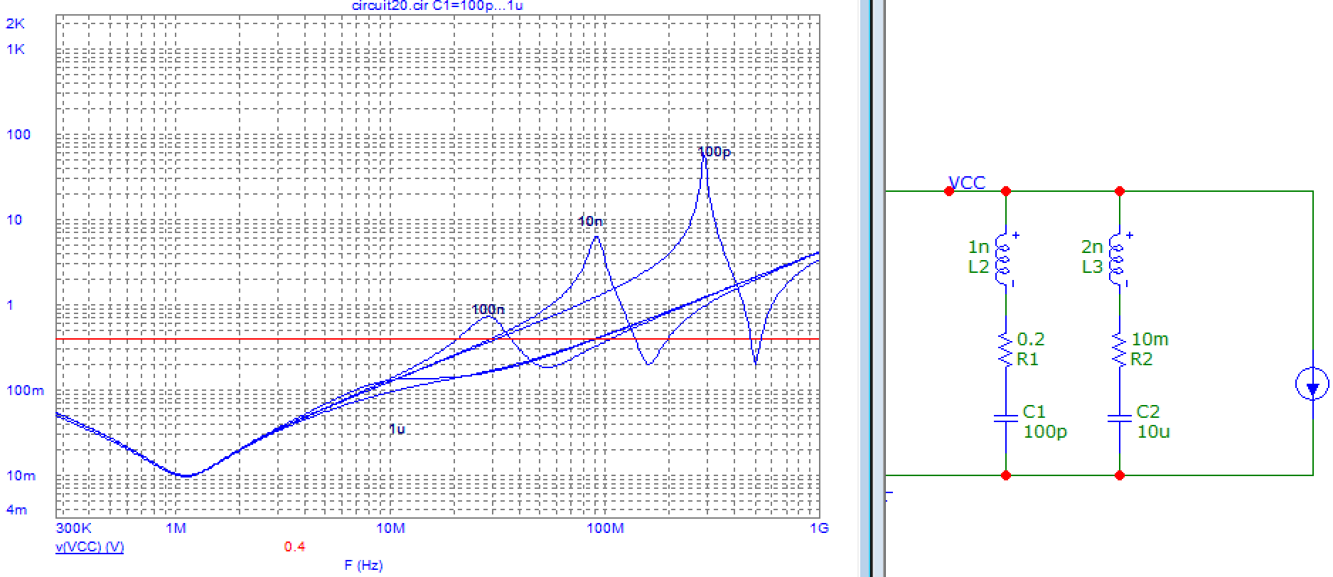
There is no mention, but is it generally recommended to also include a smaller package 100 pF or 10 pF ceramic capacitor even closer to the pins for noise filtering, as depicted below?
Bad idea. High frequency characteristics of MLCC are determined by inductance which means physical size (ie footprint). Capacitance only matters at lower frequency when inductance does not dominate total impedance. This means, if we compare two caps of the same footprint, the one with more actual µF (once biased) always wins. Using low capacitance caps is only interesting if you do a PC motherboard or big FPGA and you need 300 caps so shaving a fraction of a cent off each cap matters, which is not the case here. Or for RF where you may need a carefully tuned decoupling cap, thus an accurate value, thus C0G not X7R, thus low capacitance.
In fact pushing the larger caps away from the chip to insert the smaller caps in between may make it worse: unless you use a multilayer board with a ground plane right below top layer, most of the inductance is in the vias anyway, and the difference in inductance between a tiny cap and a larger one is not spectacular. Besides, mixing different values of caps will cause antiresonance peaks if you're not careful.

So I would recommend using one value of caps and getting a quantity discount on it. The value should be a balance between cost and the most µF that will fit in 0603 or 0805 in X75/X5R. For example, double the number of 10µF caps can be cheaper than 22µF caps due to quantity discount, and 10µF may also sustain their capacitance better under bias. Basically: optimize real capacitance under bias vs cost (including assembly costs).
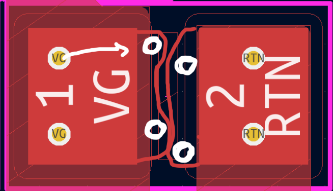
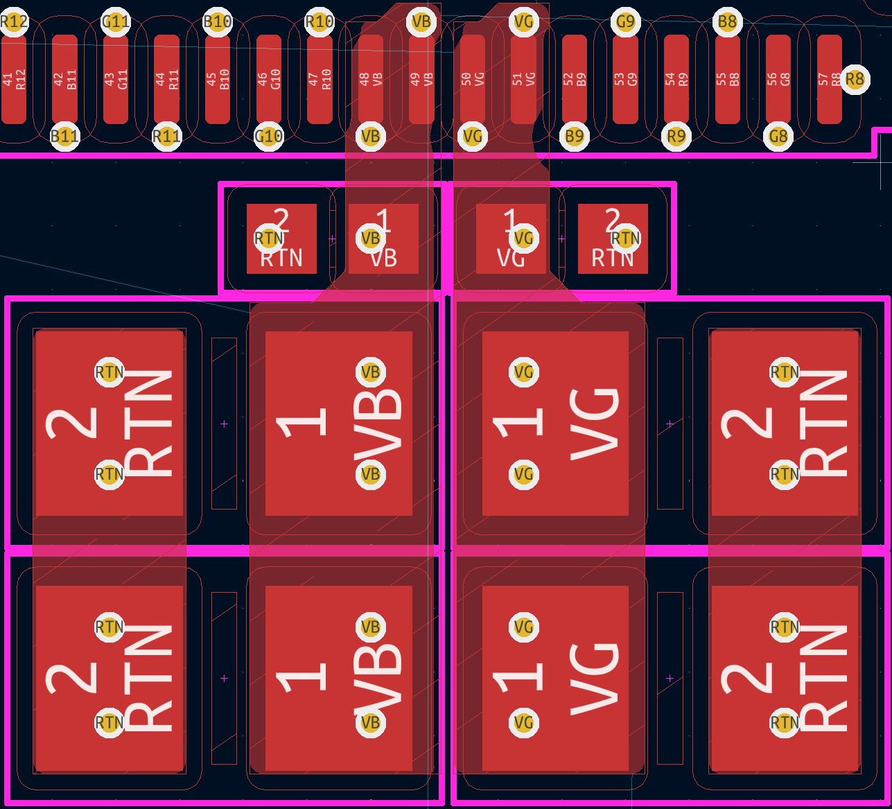
I see you're using via in pad, that will probably cost extra. Vias in the pads can suck your solder away so the cap isn't well soldered anymore. If you can have very small vias you can move them under the cap like this


