1
\$\begingroup\$

Datasheets usually specific pin leakage current for digital inputs in the Electrical Characteristics, which is generally in microamperes (µA) range. I understood from different SE posts that the specified current is usually much higher than the actual leakage current. I also understand that the leakage current direction depends on the voltage applied.

Here are a couple different examples mentioning leakage current limits in different ways.

enter image description here

Img Src: Micron DDR5 SDRAM Datasheet

enter image description here

Img Src: TI TPS51200-EP Datasheet

My general question is: Which of the following is true for the "input leakage current" specification of a digital input pin in the datasheet?

  1. Is it the maximum leakage current the pin will draw when a voltage is applied to it?
  2. Is it the maximum leakage current that must be allowed for an applied voltage?

The reason I ask this is because if were to pull up a pin with a resistor to a voltage, there would be a voltage drop across the resistor due to the leakage current that flows through the resistor. So, for example, an EN input has 10 µA maximum leakage current and I connect it to 1.8 V via a 100 kΩ pullup resistor, that would cause a drop of 1 V across the resistor in the worst case and the EN pin would not detect it as HIGH since it would see only 0.8 V whereas the VIH could be, for example, 1.2 V minimum.

So, if #2 would be true, we would need to connect a resistor of 1.8 V/10 µA = 180 kΩ, which would then violate the VIH specification in case a leakage current close to 10 µA flows into the pin. And conversely if I connect a lower value resistor such that VIH is met, which makes sense, it would mean a higher leakage current could flow.

Am I misunderstanding anything here? Could someone please clarify this for me?

EDIT: Summary of what I wanted to clarify and have understood based on the answers/comments. Hope it is correct: Basically, the leakage current is not something that can be or needs to be limited externally and only the maximum specified leakage current will flow for an applied voltage virtually irrespective of the external pull-up/down resistor value. Any external pull-up/down resistors should be sized such that VIH/VIL is not violated for the maximum leakage current that can flow through those resistors.

\$\endgroup\$
2
  • 1
    \$\begingroup\$ The datasheet specifies the current assuming a 0 Ohm load. Calculate your pullup resistor to give an acceptable voltage drop based on the leakage current. \$\endgroup\$
    – Kartman
    Commented Mar 26 at 11:16
  • \$\begingroup\$ Okay, good point with "0 ohm load". Thanks. Actually, I do know that pullup resistor needs to be calculated considering leakage current and corresponding voltage drop, but I was confused about #2 because I have read/heard about limiting leakage current to within specification. However, if we do that, it may not be possible without violating VIH/VIL, which is not acceptable either. That's why I made my post to look like what it is. \$\endgroup\$
    – LoveEnigma
    Commented Mar 27 at 6:32

3 Answers 3

2
\$\begingroup\$

The datasheet specifies a maximum +XμA, and a minimum of -YμA. If that's what the datasheet says, then you can trust it, unless the device is damaged, or being used in some unconventional manner, unsupported by the manufacturer.

It's true that leakage current magnitude and direction can and will change depending on pin potential.

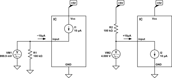
I've always assumed that (unless otherwise noted) if the datasheet gives a single, positive figure for maximum leakage current, say \$I\$, then \$-I\$ could also flow.

You are correct when you say that a resistor in series with the input will develop a potential difference in proportion to that leakage current, and that will affect the potential actually seen at the pin itself. Using a lower resistance in order to mitigate this, may result in more leakage current, but that is not necessarily always the case. Leakage current is unlikely to have an ohmic relationship with applied potential.

A couple of examples:

schematic

simulate this circuit – Schematic created using CircuitLab

This certainly can cause input potential to lie inside the range \$V_{IL}\$ to \$V_{IH}\$, which is an indeterminate condition, and you are right to be concerned by it.

While my next point has nothing to do with leakage current, it is also worthy of note: having a resistance in the path of input current will slow signal slew rate, due to input capacitance. Using an excessively large pull-up or pull-down resistor can be very detrimental:

schematic

simulate this circuit

Q1 represents an open-drain output from something or other, usually requiring a pull-up resistor. The transistor is switched on and off by input X, which here is a square wave at 10kHz:

enter image description here

The signal at the drain, which is the IC's input Y, looks like this:

enter image description here

The transistor is able to pull Y down to 0V, by discharging input capacitance C1 very rapidly through its low on-resistance, but the rising edges are really slow. We have to rely on current severely limited by R1 to charge that capacitor up to +5V. That might not be a problem in many applications, but if you have the need for speed, then resistance is very problematic.

The time it takes for the capacitor to charge to 63% of "full" (5V) is the time-constant \$\tau\$:

$$ \tau=R_1C_1 $$

Obviously, a smaller resistance is beneficial here too, which makes two good reasons for using as small a resistance as possible, while still complying with other requirements, such as circuit power consumption.

\$\endgroup\$
1
  • \$\begingroup\$ Thank you for the answer. While I understand the implications of your extended answer with higher value pull-ups, I appreciate that you mentioned it. "Using a lower resistance in order to mitigate this, may result in more leakage current, but that is not necessarily always the case. Leakage current is unlikely to have an ohmic relationship with applied potential." -> I believe this was the key takeaway for me and what I wanted to get clarified. So, the external resistors should be sized such that they don't violate VIH/VIL based on the maximum leakage that is expected to flow through them. \$\endgroup\$
    – LoveEnigma
    Commented Mar 27 at 7:01
2
\$\begingroup\$
  1. Is it the maximum leakage current the pin will draw when a voltage is applied to it?

Yes. Input leakage current in CMOS devices represents the current that can flow into or out of the pin when a voltage is present there.

The leakage currents, quite possibly, come from either the input transistors or the protection diodes (if any) or both.

For RESET_n pin of the DDR5 SDRAM, for example, assuming the input has protection diodes tied to both rails (not mentioned in the datasheet but let's assume for a moment), if the input voltage is at 0V then the high-side diode will be reverse biased so the leakage current will flow out of the pin, hence the negative sign. Likewise, when the input voltage is at a higher level then the low-side diode will be reverse biased so the leakage current will flow into the pin, hence the positive sign.

The logic inputs, despite the FETs have high input impedances, may still draw some non-zero leakage currents. Apart from that, the internal pull-ups/pull-downs will bring extra leakages. A good example is shown in the DDR5 SDRAM datasheet: If you check the Table 274 you'll notice that some logic inputs have extra leakages due to the weak pull-ups/pull-downs.

So, for example, an EN input has 10 µA maximum leakage current and I connect it to 1.8 V via a 100 kΩ pullup resistor, that would cause a drop of 1 V across the resistor in the worst case and the EN pin would not detect it as HIGH since it would see only 0.8 V whereas the VIH could be, for example, 1.2 V minimum.

Then you shouldn't use that high pull-up. For any external pull-ups/pull-downs that you'll connect, take the leakages into account and use suitable values not to violate the input voltage range requirements (VIL & VIH).

\$\endgroup\$
8
  • \$\begingroup\$ Thank you for your answer. Yes, I do understand about considering leakage current for pull-ups/pull-downs, but I framed my post intentionally in that way. \$\endgroup\$
    – LoveEnigma
    Commented Mar 27 at 6:53
  • 1
    \$\begingroup\$ @LoveEnigma sometimes I have read about liming/reducing the leakage current to meet a specification or something. I have never seen/read such a thing. Please give an example. we don't need to "limit" the current through the resistor to the input leakage current value specified in the datasheet, right? Leakage is not under your control except in some extreme situations (e.g. applying high voltage). It comes from the real-world imperfections. The leakage specs are given for certain conditions such as applying voltage "directly" i.e. through zero Ohms. But this doesn't mean less leakage if + \$\endgroup\$ Commented Mar 27 at 8:05
  • 1
    \$\begingroup\$ + the voltage is applied through a non-zero resistance e.g. pull-down or pull-up. If the RESET_n pin sees, say, 3.3V it may draw a maximum leakage of, say, 5 microamps. So no, it's not a thing that you can or should somewhat limit. If it's going to flow, it's going to flow. \$\endgroup\$ Commented Mar 27 at 8:08
  • 1
    \$\begingroup\$ @LoveEnigma In EDSFF spec. SFF-TA-1009 (free download), Table 6-4, input leakage current limit is mentioned as -/+ 100 microamps. Oh, this is totally a different thing: If I understood correctly, a specification that your equipment should comply. The translation of "leakage requirements" there is something like "make sure the leakage currents of your equipment's digital inputs don't exceed these limits." which is another way of saying "carefully design/select/size the components, logic sections and protection elements and mind the leakages.". The leakage, again, is not under your control + \$\endgroup\$ Commented Mar 27 at 9:47
  • 1
    \$\begingroup\$ + which means you just select the components during the design process but taking the leakages into account as well. If you'll have protection/clamping diodes on each logic input then you should use ones with low enough leakage current rating. If you are designing an equipment as per the spec you mentioned then the 3V3 logic inputs/outputs "must" have their leakage ratings within the limits. So you should "select" or "design" the related sections accordingly. Then you specify the ratings in your equipment's datasheet, the rest is under the responsibility of those who will use your device. \$\endgroup\$ Commented Mar 27 at 9:53
1
\$\begingroup\$

You have two different values for two different pins.

And you must calculate the resistor so that it still exceeds any logic threshold you want.

If you need a pull-up to 1.8V, and must be above 1.7V, you have 0.1V allowed drop over resistor at any leakage current. 0.1V / 10uA is 10 kohms.

So yes,

  1. for any applied voltage there could be max leakage current going into or out of chip. This includes applying 0V.
  2. It makes sense yes to assume at any applied voltage the pin could leak the maximum leakage current.

Which means, if you intend to connect 1000 pins on same bus, each with leakage of 1uA max, your output needs to be strong enough to be able to drive 1mA in theory while making sure the voltage on bus is within logic level margins.

\$\endgroup\$
2
  • \$\begingroup\$ Sorry, but those were only examples used to quote my "general" questions. I do understand your point, but I intentionally framed my post the way it is. Not sure if framing it differently would have helped avoid any confusion or lack of understanding on my part. Thanks for your answer though. \$\endgroup\$
    – LoveEnigma
    Commented Mar 27 at 9:05
  • 1
    \$\begingroup\$ @LoveEnigma I don't see what confusion there is. You must size your own pull-ups or pull-downs so that the pin voltage is what it needs to be when current leaks in or out of the pin. \$\endgroup\$
    – Justme
    Commented Mar 27 at 9:18

Your Answer

By clicking “Post Your Answer”, you agree to our terms of service and acknowledge you have read our privacy policy.

Not the answer you're looking for? Browse other questions tagged or ask your own question.