5
\$\begingroup\$

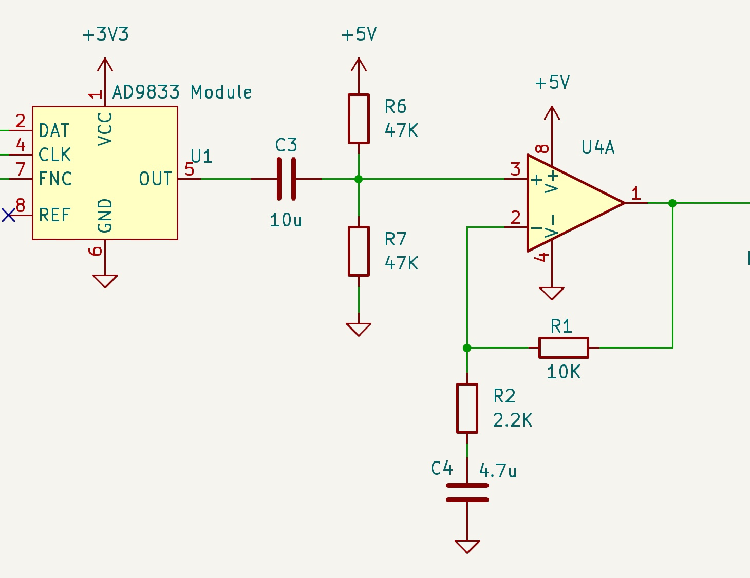
I'm trying to amplify a sine wave signal with opamps of high bandwidth and slew rate. It works fine up to about 700 kHz, then the gain decreases and about 1 MHz it's only 1, when it should be about 5.

I'm testing with the circuit below and two different opamps, with similar results: LMH6658 (bandwidth 270 MHz, slew rate 700 V/μs) and AD8066 (bandwidth 145 MHz, slew rate 180 V/μs).

LMH6658: https://www.ti.com/lit/ds/symlink/lmh6658.pdf?ts=1711450406602

AD8066: https://www.analog.com/media/en/technical-documentation/data-sheets/ad8065_8066.pdf

Test circuit

I don't know if I miss something. Should I expect to be able to get a gain of 5 with these opamps up to 5 MHz?
I'm testing in a breadboard. The input signal is about 600 mV, and the sine wave is clean and not distorted in the output, even above 1 MHz.

Could be that the opamps are fake/relabeled, but before returning and ordering them in Mouser I wanted to make sure. I don't know if there could be other problems. I understand that the opamps with that bandwidth and slew rate should be enough for these frequencies, but I'm not sure. Thanks!

Edit: I add some concrete numbers. Checking it better I see the performance of both opamps is different (after many tests I had a mix of results in my head). LMH6658 is much better, but anyway the gain starts to decrease below 500KHz.

LMH6658 (input signal ampl -> output signal):
    100KHz: 680mV -> 3.32V
    400KHz: 680mV -> 3.24V
    600KHz: 680mV -> 3.16V
    800KHz: 640mV -> 3.00V
    1MHz:   600mV -> 2.84V
    2MHz:   480mV -> 2.16V

AD8066:
    100KHz: 680mV -> 2.56V
    600KHz: 680mV -> 1.30V
    800KHz: 640mV -> 1.00V
    1MHz:   600mV -> 760mV
    2MHz:   480mV -> 360mV
\$\endgroup\$
4
  • \$\begingroup\$ Please link data sheets for the op-amps. Your gain should be 5.45 btw. \$\endgroup\$
    – Andy aka
    Commented Mar 26 at 12:19
  • \$\begingroup\$ What kind of breadboard setup?...neither of these chips have dual-inline packages that plug into solderless breadboards that most of us imagine when you say "breadboard". \$\endgroup\$
    – glen_geek
    Commented Mar 26 at 13:06
  • \$\begingroup\$ I solder them to SOP8 to DIP adapters. If I continue it I will create a PCB. \$\endgroup\$
    – Gos
    Commented Mar 26 at 14:47
  • \$\begingroup\$ I have added some concrete numbers to the post. But it looks strange to me is that the reduction of the gain starts before 500KHz, a not so high frequency. \$\endgroup\$
    – Gos
    Commented Mar 26 at 15:14

2 Answers 2

6
\$\begingroup\$

On a breadboard you can expect lots of capacitance between each pair of rows of connectors, perhaps 10pF. With your feedback resistance of 10kΩ, combined with capacitances of that order, an estimate of cut-off frequency might reasonably be:

$$ f = \frac{1}{2\pi \times 10k \times 10p} = 1.6MHz $$

There will be similar attenuation anywhere where the signal path contains significant impedance. You could try reducing R1 and R2 by a factor of 2, or 5, for example, just to see if the situation improves. If it does, then you'll have to find a better way to prototype the circuit.

\$\endgroup\$
14
  • \$\begingroup\$ Ok. I have tried with 2.2KΩ and 470Ω and the gain increases a bit, but also the expected gain 5.68 and before was 5.45. \$\endgroup\$
    – Gos
    Commented Mar 26 at 15:00
  • \$\begingroup\$ @Gos I don't follow you. At what frequency does gain drop to 70% of expected (-3dB)? And how are you measuring? Oscilloscope? Probes on X10 or X1? What's the setup? In fact, put all this information in your question, because people are bound to ask. \$\endgroup\$ Commented Mar 26 at 15:09
  • \$\begingroup\$ I have added concrete numbers. The probes are set to X1. The oscilloscope it's a Siglent, 200MHz, 1 Gs/s. \$\endgroup\$
    – Gos
    Commented Mar 26 at 15:18
  • \$\begingroup\$ I mean that with 10KΩ, 2.2KΩ the expected gain would be 5.45. And with 2.2KΩ and 470Ω would be 5.68. What explains the small improvement. \$\endgroup\$
    – Gos
    Commented Mar 26 at 15:19
  • \$\begingroup\$ @Gos Higher cut-off frequency could explain it. So could component tolerances. 1% resistors, or 5%? Anyway, the acid test is to find cut-off frequency exactly, and see if it increased. With an expected gain of 5.5, cut-off will be when gain is 3.9, or amplitude is 0.6*3.9 = 2.34. \$\endgroup\$ Commented Mar 26 at 15:28
7
\$\begingroup\$

A couple of reasons.

First, the schematic shows no bypass caps on supply.

Second, you have built the circuit on a breadboard. You can't expect high performance analog or digital operation.

Third, it depends how you are measuring it. 1x scope probes may have around 5 MHz bandwidth anyway.

You said you were measuring with 1x probes. That is likely the problem that limits the bandwidth. As a rule of thumb, never use 10x/1x probes in 1x mode unless you are in a situation where you know you need to use it.

You said you are using electrolytic bypass caps. A general purpose electrolytic may be useless at 1 MHz. It also makes things worse if the electrolytic is on breadboard, with long wiring through breadboard and adapter to IC. A 100nF ceramic right on the adapter might make a difference, if there is no improvement from switching probes to 10x.

\$\endgroup\$
6
  • \$\begingroup\$ I have 10uF capacitors in the power rails, one close to the Vcc pin. I suppose that the breadboard and probe could have some impact. But actually the gain start to decrease below 1MHz. I add more concrete numbers in the post. \$\endgroup\$
    – Gos
    Commented Mar 26 at 14:49
  • \$\begingroup\$ @Gos You didn't show the capacitors on the schematic or did not tell about them. What type/kind capacitors they are? Electrolytic? \$\endgroup\$
    – Justme
    Commented Mar 26 at 17:44
  • \$\begingroup\$ Yes, sorry. They are electrolytic. I will try to solder the components directly to the sop-8 adapter, and also a ceramic capacitor from VCC to GND pins. \$\endgroup\$
    – Gos
    Commented Mar 27 at 6:52
  • \$\begingroup\$ @Gos Standard electrolytics are of no use as bypass caps at 1 MHz to begin with, and being plugged to op-amp through breadboard wiring only makes it worse. \$\endgroup\$
    – Justme
    Commented Mar 27 at 7:51
  • \$\begingroup\$ @Gos You said in another comment your probes were set to 1x mode. That definitely is the largest problem. Which is what I already said in my answer as one possible explanation. \$\endgroup\$
    – Justme
    Commented Mar 27 at 8:33

Your Answer

By clicking “Post Your Answer”, you agree to our terms of service and acknowledge you have read our privacy policy.

Not the answer you're looking for? Browse other questions tagged or ask your own question.