4
\$\begingroup\$

Suppose we have two transmission lines connected with each other, each transmission line has the same characteristic impedance: $$ Z_0 = \sqrt{\frac{L}{C}} $$ however they don't have the same dielectric and therefore the wave impedance: $$ \eta = \sqrt{\frac{\mu}{\epsilon}} $$ is different. This therefore implies that according to transmission line theory, since there is no characteristic impedance mismatch, there shouldn't be a reflected wave at the interface between both lines. On the other hand, general EM theory, predicts that there should be a reflection since both materials have different wave impedances, seemingly contradicting what transmission line theory predicts. So what's going on and who's right?

For instance, the characteristic impedance of a coax cable is: $$ Z_0 = \frac{\ln{ \left ( \frac{R_{out}}{R_{in}} \right )}} {2 \pi} \eta $$ If we fix \$ R_{out} = 10mm \$ for both lines and set \$ \epsilon_r = 2 \$ for the first line and \$ \epsilon_r = 4 \$ for the second line, then we get \$ R_{in} = 1.70508mm \$ for the first line and \$ R_{in} = 0.819452mm \$ for the second line, both having the same characteristic impedance of \$ 75 \Omega \$ whilst their wave impedance is different.

My guess is that this might be solved via Imbalance Difference Modeling which enables a more general perspective to transmission line theory. All thoughts are welcome.

\$\endgroup\$
4
  • 1
    \$\begingroup\$ But if the characteristic impedances are identical, how would the end of transmission line 1 know if there is a termination resistor of characteristic impedance, or it continues with transmission line 2 with same characteristic impedance, or another piece of transmission line 1 with same characteristic impedance? \$\endgroup\$
    – Justme
    Commented Mar 26 at 13:27
  • \$\begingroup\$ @Justme you’re right, the transmission line sees the same impedance regardless of whether there is a termination (matching the characteristic impedance) or a second transmission line with the same characteristic impedance. I’m not sure how this connects with the question though. \$\endgroup\$
    – rr1303
    Commented Mar 26 at 13:53
  • \$\begingroup\$ Also, this is essentially a duplicate of: electronics.stackexchange.com/questions/543346/… \$\endgroup\$ Commented Apr 3 at 9:45
  • \$\begingroup\$ @TimWilliams They are certainly linked and quite similar to one another, so it's good to have the other question referenced here. However I wouldn't consider them as (true) duplicates, the other question focuses on geometric discontinuities and this question looks at dielectric discontinuities. \$\endgroup\$
    – rr1303
    Commented Apr 3 at 10:54

5 Answers 5

5
\$\begingroup\$

your \$\eta\$ formula is for a wave freely travelling in a medium. That's not the case for a transmission line, so you're applying the wrong formula there. The physics doesn't "care" about some property under different boundary conditions than the ones you have; you're building waveguides, not letting waves propagate in infinitely extending homogeneous media.

If both transmission lines have the same characteristic impedance, they have the same characteristic impedance, no matter their materials. The material is not the only thing that defines it – the geometry of the transmission line matters just as much; if you go from an air-filled hollow waveguide to a PTFE-filled one, the cross-section will have to shrink to keep the same characteristic impedance. But it's possible, and commonly done, to convert waves from one waveguide material to another.

\$\endgroup\$
7
  • \$\begingroup\$ Interesting, then what would be the correct expression for \$ \eta \$? Wikipedia points out that for a TEM (like the ones within a transmission line) the wave impedance matches the intrinsic impedance of the material (it doesn’t say the same for TE and TM modes though). \$\endgroup\$
    – rr1303
    Commented Mar 26 at 13:59
  • \$\begingroup\$ the expression is correct. it just doesn't matter here :) And you'll really have to point out specifically where wikipedia says that, because I literally just am looking at the Wave Impedance article, and while it's really badly structured, it doesn't say that. \$\endgroup\$ Commented Mar 26 at 14:00
  • \$\begingroup\$ In that same article, first paragraph at the very beginning: “For a transverse-electric-magnetic (TEM) plane wave traveling through a homogeneous medium, the wave impedance is everywhere equal to the intrinsic impedance of the medium.” \$\endgroup\$
    – rr1303
    Commented Mar 26 at 14:15
  • 1
    \$\begingroup\$ "travelling through a homogeneous medium" is not the same as "travelling through a waveguide filled with a medium" \$\endgroup\$ Commented Mar 26 at 16:09
  • 1
    \$\begingroup\$ Right, that's the key here! The wave is confined within the waveguide and the general unbounded reflection coefficient \$ \Gamma = \frac{\eta_2 - \eta_1}{\eta_2 + \eta_1} \$ is therefore of little to no use. Is this the correct idea? \$\endgroup\$
    – rr1303
    Commented Mar 26 at 17:02
3
\$\begingroup\$

This is an electromagnetic problem, not a circuit theory problem. Treating your transmission lines as circuit theory elements is fine for continuous lines but breaks down at junctions. In general you will get reflections at a junction like you describe.

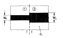
Instead of your coaxial example, I'll talk about microstrip as it may be easier for PCB folk to visualise. If you have a microstrip track at \$Z_0\$ on FR4 (\$\epsilon_r = 4.3 (ish)\$ and suddenly the substrate changes to \$\epsilon_r = 2\$ with the same substrate thickness, then the track suddenly gets substantially wider.

enter image description here

Although circuit theory suggests that you have simply connected two transmission lines with the same characteristic impedance, maxwell's equations at the junction say something different. It quickly gets complicated, but the exposed end of the wide line has fringing electric fields that can often be modeled as a shunt capacitance, and the current spreading out from the narrow line to the wide line results in extra stored magnetic energy that may appear as a series inductance. Clearly the current distribution in the wide line at the junction is nothing like that far away from the junction.

If you want to model this for any transmission line for which you have a full modal solution, look up waveguide mode matching. This would let you model your coax junction, as would some sort of finite element simulator.

Another application is the transition from a coax cable to microstrip. If what the circuit theorists are saying was true, then it would be trivial to mount a coax connector (e.g. sma) to a PCB, connect to a 50 ohm microstrip trace and obtain a broadband, reflection free, transition. Those who have actually tried this in a lab know that this is not easy to even approximate.

The picture is from N. H. L. Koster and R. H. Jansen, "The Microstrip Step Discontinuity: A Revised Description," in IEEE Transactions on Microwave Theory and Techniques, vol. 34, no. 2, pp. 213-223, Feb 1986

which isn't particularly useful for the case where the dielectric constant changes, but it did have a useful picture.

\$\endgroup\$
2
\$\begingroup\$

If the two transmission lines have the same characteristic impedance, then if you can connect them without introducing any other impedance in the transition region, there will indeed be no reflection at the junction.

Connecting two geometrically or dielectrically different lines together, albeit of the same impedance, is not easy to do without creating at least a little bit of 'wrong impedance' transition.

There are several solutions manufacturers and engineers have employed to get round this problem, in particular connector manufacturers, who have to handle board-to-connector, then connector-to-connector transitions.

One option is the use of a short length of deliberately different impedance, to tune out the unavoidable glitch in impedance when the geometry changes. This works only up to a limited frequency. In the simplest case where two coaxial or microstrip lines of different geometry meet, extending the smaller centre conductor in the larger outer to create an extra bit of high impedance line aka inductance serves to turn the extra stray capacitance of the discontinuity into a matched low pass filter. This is known as a 'Krauss step'.

Another option is a smooth transition, taking at least λ/4, preferably more, for a progressive transition between the two geometries.

\$\endgroup\$
1
\$\begingroup\$

The velocity of propagation, \$V_P\$ in a t-line is \$\frac{1}{Z_0\cdot C}\$ and this does not cause a reflection at the junction where two t-lines of equal \$Z_0\$ but unequal \$V_P\$ meet. It's a simple as that; ohms law does not find an "anomaly" at the junction and no reflection is required to be made. The wave continues into the 2nd t-line at a different velocity.

\$\endgroup\$
1
\$\begingroup\$

Right, the wave spreads out into the higher-bulk-impedance but shorter/wider perimeter, which balance each other out for zero total effect.

That's still a very hand-waving explanation, but may help direct your intuition.

I suppose there will still be a small change, a perturbation, but this can be ascribed to the non-uniformity of the wave within the transmission line: the wave does not change and spread out instantaneously around the discontinuity, but gradually.

And just based on how this is phrased, we would expect any such effect to depend on frequency, getting more noticeable as frequency rises.

It's important to understand that transmission line is a waveguide; waves do not propagate freely, but are confined in the space between two conductors. In particular, the cross-sectional radius and circumference of the transmission line must be less than a fraction of a wavelength to support the TEM00 mode, exclusively.

When there is a frequency-dependent effect, we can probably match a corresponding geometric dimension to it. There's only one dimension we can pull out of the boundary conditions so described: the diameters of the two transmission lines, or their difference. This isn't much to go on, and suggests that, if anything crazy happens, it happens at very high frequencies. But we also know that crazy stuff happens at high frequencies anyway: above the mode breakup cutoff, TE and TM modes arise, and velocity and impedance are all over the place.

So, at best, we would be probing the asymptotic tail of any effect, operating below the breakup frequency where the transmission line is still well-behaved as we expect a transmission line to behave. Above breakup, sure there will be a difference, but it's either obscured by the chaos of mode breakup itself, or sensitive to unaccounted-for errors (like the relative position and angle between transmitter and receiver on the line, or asymmetry in the line geometry itself), or simply not useful to us at all -- because we generally seek to avoid operating transmission lines above mode breakup.

When we derive simple models, like the familiar coaxial transmission line formula, we make various simplifying assumptions about the system; one such assumption is that cylindrical symmetry is obeyed, i.e. the wave sees a constant boundary or cross-section at any position along the line, and at any instant in time (and in both directions, but nonreciprocal lines are hard to make, heh). Clearly this is violated if we change medium and geometry partway through; this isn't at all an explanation of what will happen, but does suffice to explain why it can't be a simple one- or two-dimensional solution anymore, and we must invoke a full field solution instead.

We may still gain insight with one last low-dimensional adjustment: if we account for losses of the materials (including skin effect), we find the velocity and impedance are not independent of frequency, but indeed vary: dispersion. The dispersion of the two lines may not match, and thus we can express the perturbation as a frequency-dependent impedance mismatch.

\$\endgroup\$

Your Answer

By clicking “Post Your Answer”, you agree to our terms of service and acknowledge you have read our privacy policy.

Not the answer you're looking for? Browse other questions tagged or ask your own question.