1
\$\begingroup\$

I am working on a frequency generator to control piezoelectric transducers. I use an Arduino Uno R4 Minima to send data to an AD9833 which creates my desired sine wave up to the required 1.5 MHz.

However, the output of the AD9833 is only 0.6 V, which is far below the sought after 30 V for the transducers. So I started researching signal amplification and found op-amps to be the solution to my problem.

I did the math (which you find below) to find one which should satisfy my needs, ordered them, however, now the signal is absolutely unusable. edit: thanks to user "Andy aka", I know I will not be able to go directly from 0.6V to 30V, I plan on using 2 consecutive OpAmps with a gain of 10: 0.6V -> 6V and the second with gain 5: 6V -> 30V this way I should be withing the bandwidth of the OpAmps

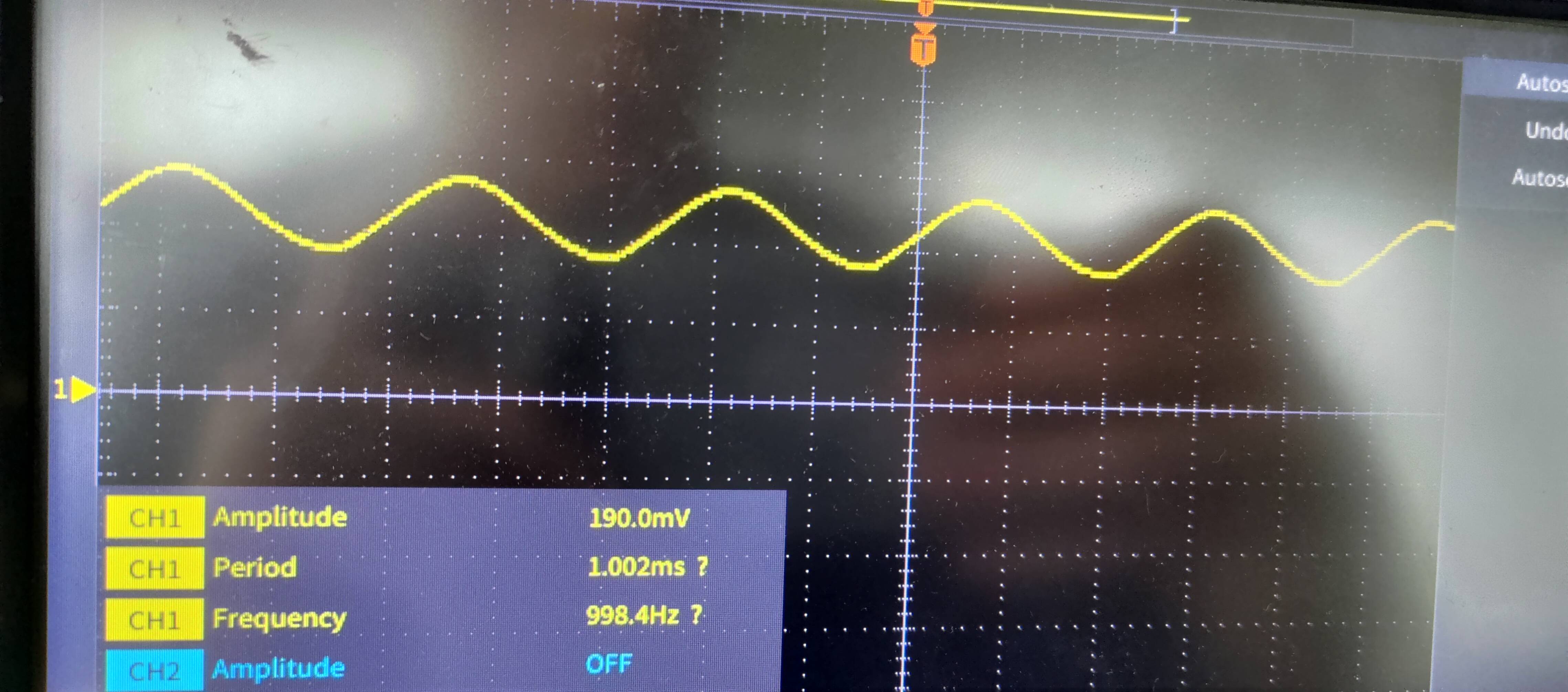
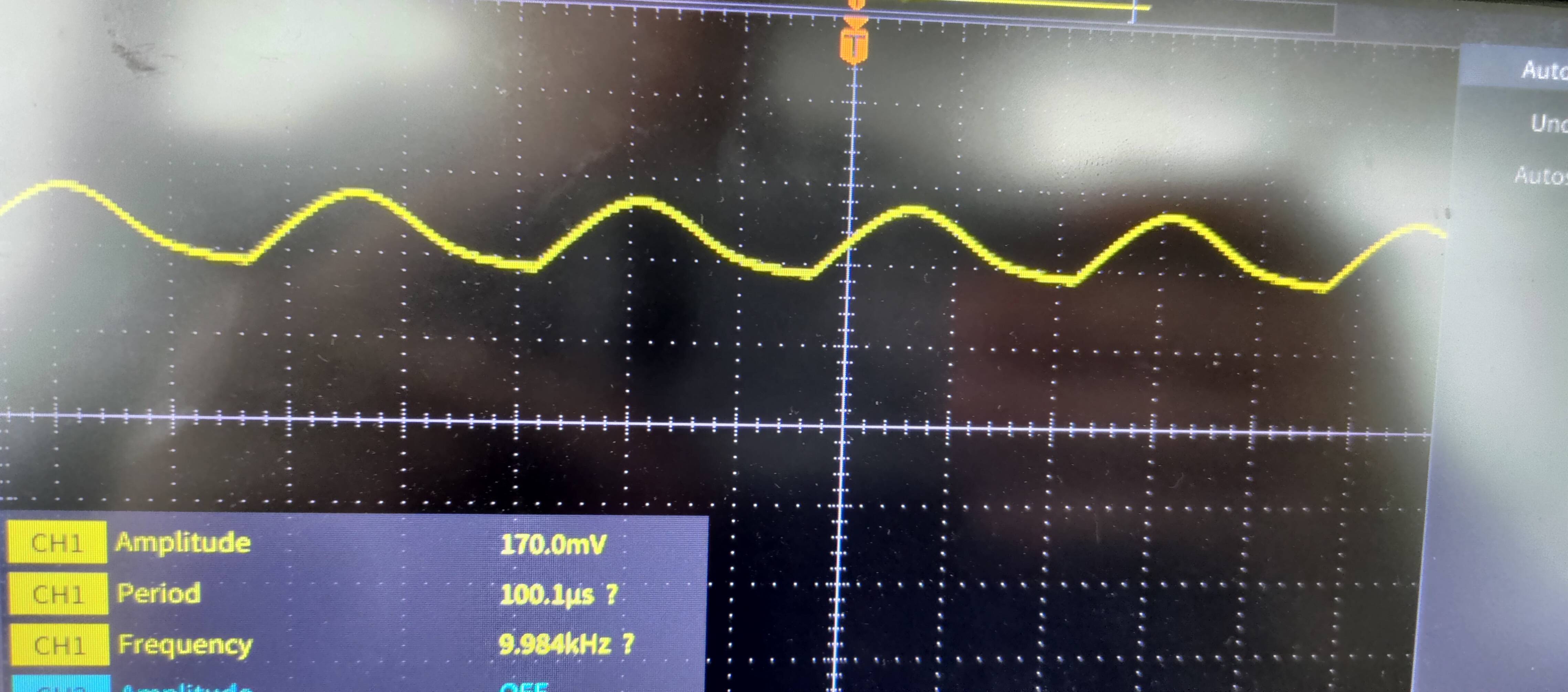
I ordered the LT1357CN8 and used it in a closed loop circuit to amplify the signal from the AD9833. The following three pictures showcase at (relatively) low frequencies of 1 kHz the sine wave is very nice, at 10 kHz you see the troughs starting to be dented and at high frequencies the bottom seems to be completely flattened.

low frequencies all fine

signal is useless

How might I solve this problem? Is the op-amp limiting?

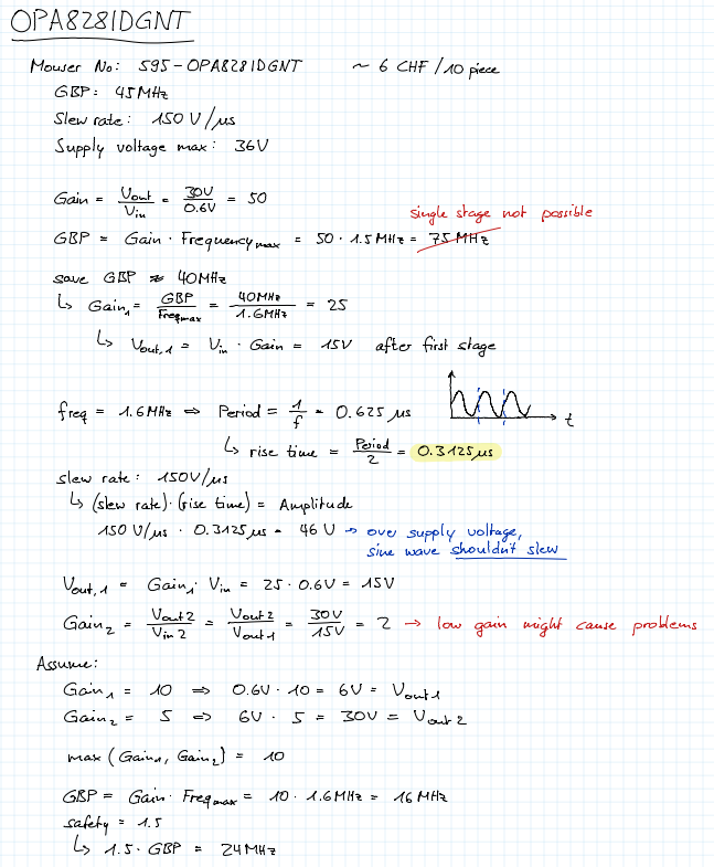
Calculation for an OPA828 which I found to be overkill for my case:

calculation for an OPA828 which I found to be overkill for my case

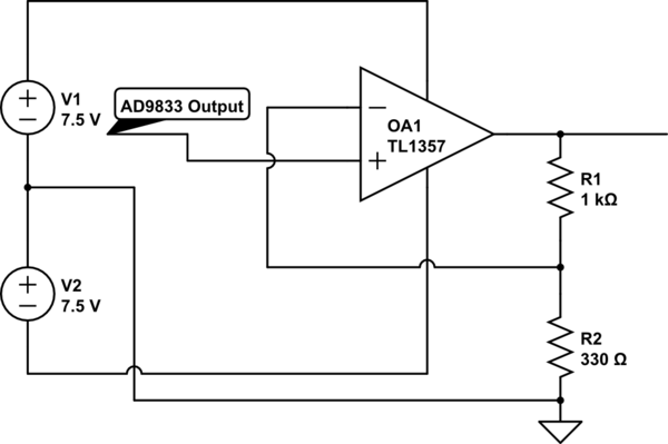
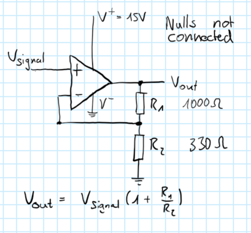
The schematic of my OpAmp circuit, Vsignal is the output of the AD9833, since this works fine I haven't added it in the schematic.only using a gain of 4 right now for testing purposes. also I can easily increase the V+ with the power supply
\$\endgroup\$
4
  • \$\begingroup\$ It would be helpful if you posted a schematic. There is a schematic tool available in this forum. \$\endgroup\$
    – qrk
    Commented Mar 27 at 19:58
  • \$\begingroup\$ @qrk I have added the schematic for the OpAmp, I hope this helps \$\endgroup\$
    – ForzenikHD
    Commented Mar 28 at 9:14
  • \$\begingroup\$ You can't get ±15V out of that op-amp, with ±15V supplies. The best you'll get, according to the datasheet is ±13V. \$\endgroup\$ Commented Mar 28 at 9:15
  • \$\begingroup\$ @ForzenikHD Try repeating your experiments with plus/minus power supplies. i.e., +7.5V for the positive power supply voltage and -7.5V for the negative power supply voltage. Single supply power topologies require extra care to make them work properly. \$\endgroup\$
    – qrk
    Commented Mar 28 at 16:31

2 Answers 2

1
\$\begingroup\$

the output of the AD9833 is only 0.6 V, which is far below the sought after 30 V for the transducers.

That means you need a gain of 50.

However, the gain-bandwidth-product of the LT1357CN8 is only 25 MHz hence, if you want a gain of 50, the highest usable frequency will be 500 kHz but, you want 1.5 MHz: -

an AD9833 which creates my desired sine wave up to the required 1.5 MHz.

So, that's the problem.

How might I solve this problem? Is the op-amp limiting?

You need a much faster op-amp.

\$\endgroup\$
2
  • \$\begingroup\$ Thank you for your input. The way I wanted to solve this problem is by having a circuit with 2 consecutive OpAmps, one with a gain of 10: 0.6V -> 6V and the next with a gain of 5: 6V -> 30V \$\endgroup\$
    – ForzenikHD
    Commented Mar 27 at 19:04
  • \$\begingroup\$ @ForzenikHD yes I understand but, there's another potential problem if you expect the op-amp to drive a piezo directly. They have a fair bit of terminal capacitance and, that can make the op-amp circuit highly unstable (I'm also ignoring the current required to drive them). \$\endgroup\$
    – Andy aka
    Commented Mar 27 at 19:19
0
\$\begingroup\$

It finally worked, thanks to the tip of @qrk. Eventhough I used the + and - pole of the laboratory power supply, this didn't create a positive and negative voltage. So I used two batteries in series, set the middle as GND and had 2 voltage wires + and - 7.5V, the OpAmp finally amplifies the signal without distortion and the signal is a perfect sine wave.

The setup:

schematic

simulate this circuit – Schematic created using CircuitLab

\$\endgroup\$

Your Answer

By clicking “Post Your Answer”, you agree to our terms of service and acknowledge you have read our privacy policy.

Not the answer you're looking for? Browse other questions tagged or ask your own question.