1
\$\begingroup\$

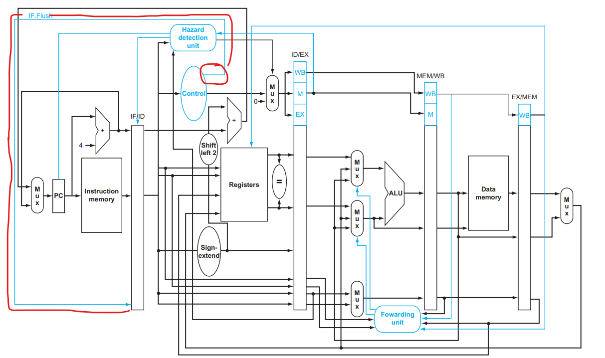
I was reading about MIPS pipelining, specifically, the part on dealing with branching through predictions by assuming a branch is not taken, then adding nops if the prediction is wrong. The IF.Flush would add all 0's to the instructions in the IF/ID register, converting the instructions stored there into nop. I thought I had it all figured out until I saw that the IF.Flush signal is coming out of the Control Unit and Not the Hazard Detection Unit. enter image description here

The questions I have are:

  • Why is the IF.Flush Signal coming out of the Control Unit instead of the Hazard Detection Unit?
  • Let's say that the Branch is in the ID stage and that not taking the branch is the correct prediction, meaning that there are no nops needed for the instruction in the IF stage. What would be the signal for IF.Flush and how does the Control Unit know that signal just from the opcode (the only line coming into the Control Unit)?
\$\endgroup\$

1 Answer 1

1
\$\begingroup\$

You ask good questions. So +1.

In contrast to the way you put your question, suppose the instruction sitting in the IF/ID latch is BEQ. And suppose that the two source resisters just happen to be the same register. Say BEQ $1, $1, addr? (Or, in some instruction sets, JMP.)

This is the same thing as an unconditional jump instruction. In fact, a separate unconditional jump instruction isn't needed, so doing it this way saves on instruction space.

(It is also conceivable to include a comparator directly inside the ID stage that looks at the two REG file read-data outputs and gives a yes/no on that compare, which can be used to anticipate the result of a BEQ or BNE before it gets to the EX stage. That could reduce one of the two bubbles otherwise needed if the ALU in the EX stage is first required.)

An unconditional jump means that the instruction following it is not needed.

Detecting an unconditional jump in the control unit reduces further delays by doing this branch test early, in the control unit, and avoids a stall (which is what the hazard detection unit does.)

The purpose of the IF.Flush is to insert a bubble into the IF/ID latch when an unconditional jump is detected, without requiring a stall. This specific detection is done by the control unit, not the hazard detection unit.

In this case, the IF/ID latch will have already latched the PC address of the BEQ and also the immediate constant present in a field of the BEQ. These two values are already being presented to an adder, so that the new PC address is also already at the adder output and ready to be presented to the instruction address register.

So the control unit will signal an IF.Flush but it will also signal a mux to pick off the appropriate adder output that currently has the branch-to address already calculated and send that along towards the instruction address register input (via other muxes.) This bypasses the usual PC counter adder, which will have already computed a different address -- but one that isn't needed.

However, the instruction address register hasn't yet latched that value. It's sitting at its input already. But it needs a clock to latch it and present it to the instruction memory.

So an IF.Flush bubble is inserted into the IF/ID for one clock. That extra clock allows the instruction memory to find and present the next instruction located at the BEQ target address and present it to the input of the IF/ID. And one more clock (the one just following the bubble) latches this target instruction into the IF/IF.

Meanwhile, the rest of the pipeline can continue for a clock, with all necessary forwarding activities still taking place.
\$\endgroup\$
7
  • \$\begingroup\$ So by the time the IF.Flush signal gets to the IF/ID, the PC still does not have the BEQ Target address because that will be done on the next clock cycle. If the multplexor that chooses PC + 4 or PC + Offset(Branch target address) chooses PC + 4, it is the next clock cycle that allows for the PC to have that as the new value, fetch the instruction from instruction memory and then latch it into IF/ID? \$\endgroup\$ Commented Apr 2 at 10:10
  • \$\begingroup\$ @JuanDeCastro No, the target address is already computed inside the ID stage. The ID stage already has access to the captured PC and also the instruction constant for the branch. These are both already provided to an adder. All that needs to be done by the control unit is to signal also the appropriate muxes to route that sum over to the PC. BEQ still in ID stage at this point. Next clock flushes IF/ID, but also latches this new PC which provides address to instruction memory. So on following clock, new instruction is latched into IF/ID. One bubble. Not two. \$\endgroup\$ Commented Apr 2 at 10:22
  • \$\begingroup\$ @JuanDeCastro Without that adder being present, then there would have to be two bubbles so that the EX phase and the ALU could provide it. But the extra adder is usually added into the ID stage just for this purpose. Too cycle-costly, otherwise. No one wants to wait for the EX/ALU stage. If the instruction memory were dual-ported, like the REG file is, then even the first bubble could be eliminated, I suppose. But that's way too expensive. \$\endgroup\$ Commented Apr 2 at 10:23
  • \$\begingroup\$ Sorry, I meant that the PC still does not have BEQ target address in it but has already been calculated, but that the address will be written into the PC on the next clock cycle. As you said in the reply "next clock cycle flushes IF/ID, but also latches this new PC which provides address to instruction memory \$\endgroup\$ Commented Apr 2 at 10:38
  • \$\begingroup\$ @JuanDeCastro Okay. So we are on the same page? \$\endgroup\$ Commented Apr 2 at 10:50

Your Answer

By clicking “Post Your Answer”, you agree to our terms of service and acknowledge you have read our privacy policy.

Not the answer you're looking for? Browse other questions tagged or ask your own question.