I am attempting to control a KVM switch using ESPHome on a D1 Mini ESP8266 board, so learning some electronics along the way.
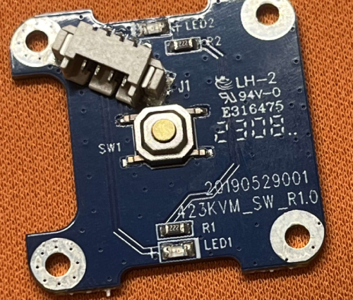
The KVM has the main unit and a controller on the end of a 4 core cable. The controller consists of a single momentary switch, two resistors and two LEDs. (a photo of this board is attached below) The resistors say 222, which having googled appear to be 2.2kohm
The 4 wires inside the cable appear to be as follows
- red - 5v
- black - ground
- green - data
- white - momentary switch
When the green wire is
- high (5v), LED1 is lit
- low (0v), LED2 is lit
I have tried to recreate the controller with an Arduino while learning so I don't break the device itself.
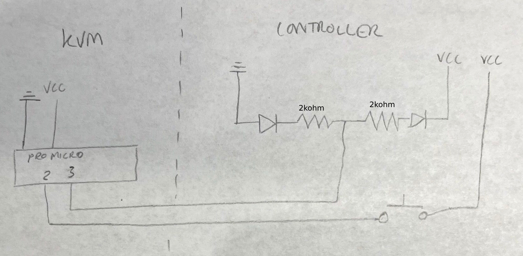
I've drawn this circuit† which I believe is how the controller board is wired. This is I suppose my first question. Is my understanding of how this is wired correct?
It functions as expected, when my button is pressed, the INPUT pin on the Arduino goes HIGH and the program inverts the OUTPUT pin for the LED and one LED switches on when the other switches off.
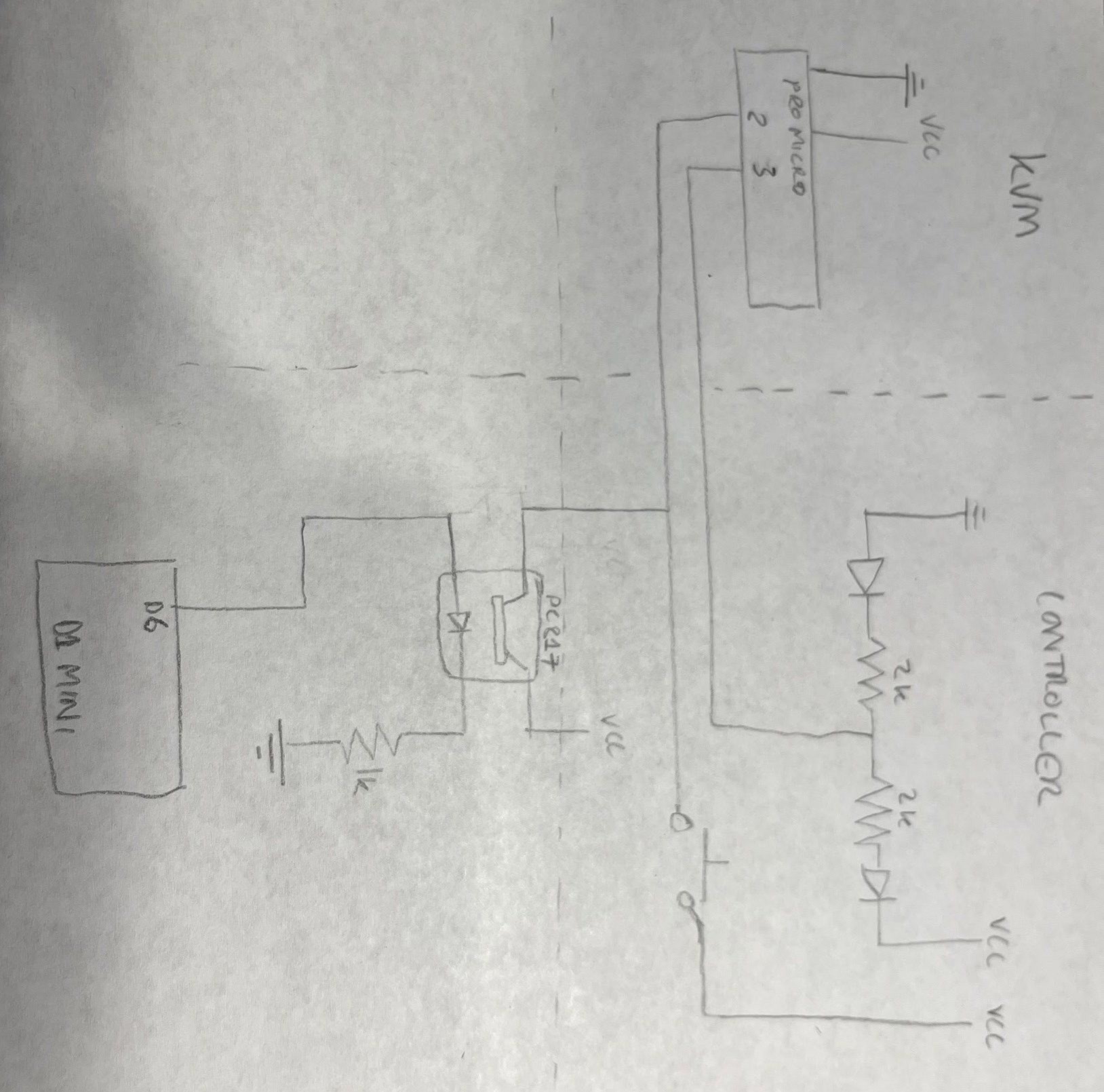
I have then added a D1 Mini flashed with ESPHome and a PC817 optocoupler to press the button independently of the circuit. This works as expected. I've added this to my diagram. I can trigger the press via ESPHome and the LEDs on the controller swap over.
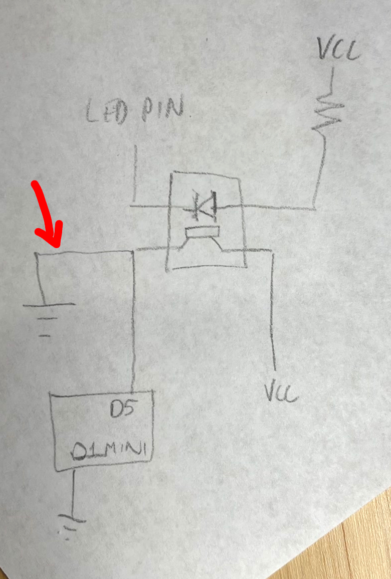
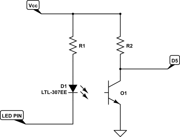
I am then trying to read the LED pin via another optocoupler. The problem I'm facing is that once I connect the second optocoupler to the LED pin, I can't get the high/low signal to register the change on the D1 Mini unless i actively connect and disconnect the ground so I'm presumably wiring something wrong and i can't work out what.
I know the optocoupler is working correctly as I can place an LED on the other side of it and have it turn on and off when the LEDs on the controller alternate when switched.
If I test the connection with a multimeter between the output of the optocoupler and the ground pin on the D1 mini, it registers 3v when the controller is on LED 1 and 0v when the controller is on LED 2 as expected.
However, nothing is registered on the D1 mini. If however I introduce a connection to ground at the point indicated by the arrow in the below diagram, I can plug that in and unplug it and get an on/off on the D1 Mini.
The fact that I can see results by adding a ground makes me think it's an physical electrical issue, hence posting here. However, in writing this and rubber ducking I wonder if actually it could be all wired correctly and just be an ESPHome/D1 Mini issue.
Any advice would be greatly appreciated as I'm just feeling my way through this project from complete scratch.
† (Apologies for the hand drawn and possibly backwards symbols)
†† I noticed after drawing the diagrams that i missed the little arrows off all my LED symbols, so those Diodes are supposed to be LEDs...
This is the binary_sensor in the ESPHome configuration in case it's of any use.
binary_sensor:
  - platform: gpio
    id: led_pin
    name: kvm_led
    pin:
      number: GPIO14
      inverted: false
      mode: INPUT

