1
\$\begingroup\$

I'm designing an H-bridge inverter circuit for a class project.

This is my circuit:

Hbridge inverter

My professor doesn't allow me to use any existing ICs apart from op-amps and the 555 timer, so that is why I'm using a basic square wave oscillator as a driver for the MOSFETS.

This is the output:

oscilloscope readinfa

  • Channel A (yellow) is the oscillator's output.
  • Channel B (blue) is the inverted oscillator's output.
  • Channel C (red) is the final output waveform. -Channel D (green) is the output of the inverter circuit before going into the transformer.

I'm still very new to electrical circuit design and don't really know how or what to debug to fix my circuit.

  • Why is it outputting a wave that looks like that?
  • How should I go about fixing it?

**Edit:

Hi, thank you guys for the responses.

As suggested by winny, i changed my high side MOSFETs from N channel to P channel. I also added a non-inverting amplifier to the minus output as suggested by Antonio51.

This is my new circuit:new circuit

And this is the new output:Updated output

  • All channels are the same as last time.

I think this is much better than before, but I still don't understand why there is a gradual voltage drop when the MOSFETs channels are on.

Again thank you guys so much for the suggestions!

**Edit 2:

Hi all, thank you for responding!

To answer Fabio Barone's questions:

  • The source is supplying 12V, and I don't think the supply is in current-limited mode but here's an image of the source's settingsSource's settings
  • The previous transformer inductances are: enter image description here
  • Since this is a school project, I'm just thinking maybe it should have enough power to turn on an incandescent light bulb (~50W)
  • I don't know how to select power ratings for resistor in proteus, I also don't know what kind of results you are looking for, can you please elaborate further ?
\$\endgroup\$
3
  • \$\begingroup\$ First of all, the voltage gain of the OPAmp in inverting configuration must be -1 and not -10, furthermore the output voltage must be filtered in such a way that only the first harmonic at 50Hz passes. \$\endgroup\$ Commented May 8 at 11:13
  • \$\begingroup\$ You should add an non-inverting amplifier for the minus output to "equalize" the delays ... Better for the "short" between Q2 - Q4 and Q3 - Q5 when changing command levels. \$\endgroup\$
    – Antonio51
    Commented May 8 at 12:24
  • \$\begingroup\$ Note that Q1 and Q6 you added in the last schematic are not "useful" ... if the voltage supply is < 16 V. \$\endgroup\$
    – Antonio51
    Commented May 9 at 8:01

4 Answers 4

5
\$\begingroup\$

Your high side MOSFETs are N-channel, so you need gate voltages above 12 V to turn them on. Presently, your opamp which drives them are driven from the same 12 V rail so they can't turn on.

Either you need to use P-channel MOSFETs for your high side or you need to supply about 24 V to the gates of Q2 and Q5.

\$\endgroup\$
0
\$\begingroup\$

Here is what I get, simulated with microcap v12.
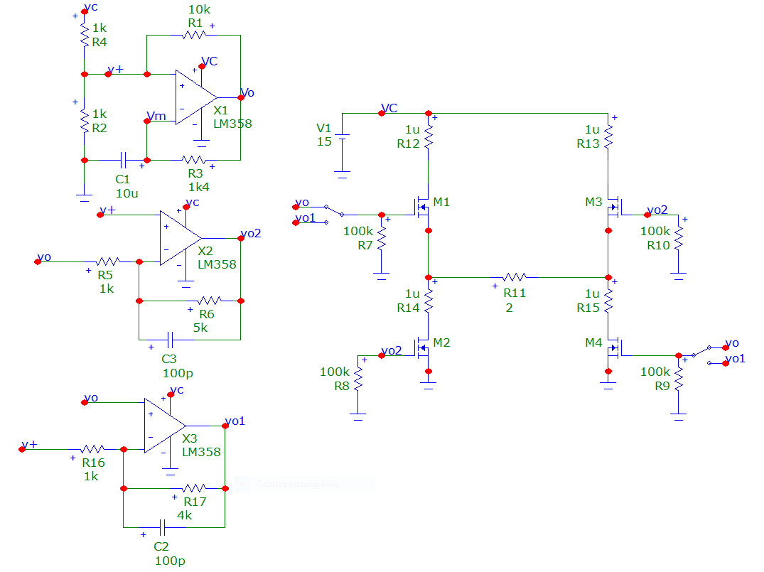
I have modified a little your circuit. Added an amplifier ...

enter image description here

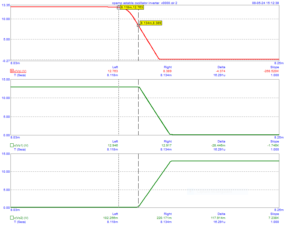
You can see why I added this amplifier in the next picture ...
See the delays ... Bridge does not "love" this (delay "vo" versus "vo1").
"vo1" versus "vo2" are more "ok".

enter image description here

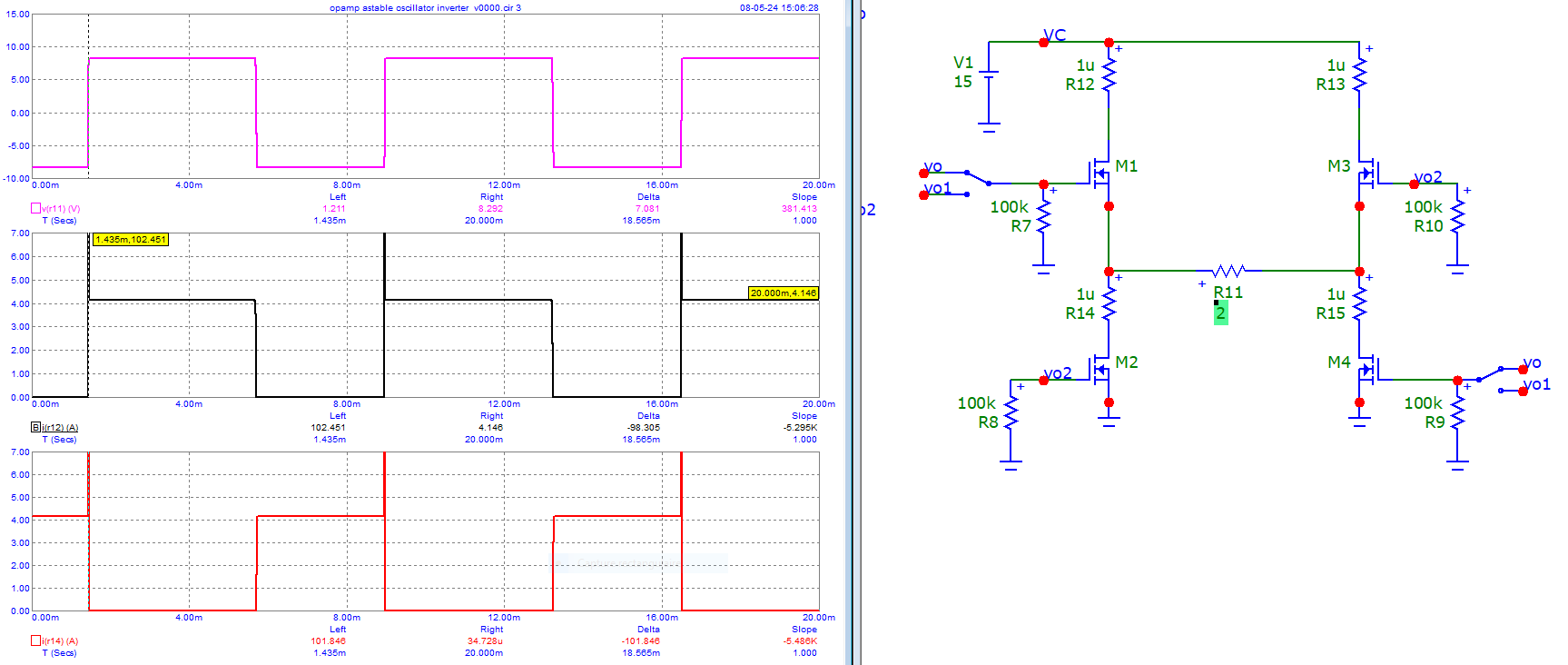
Position of switches : vo (See maxima current : 102.451 A)

enter image description here

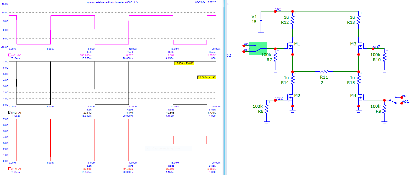
Position of switches : vo1 (see maxima current : 23.812 A)

enter image description here

Better than preceeding ... but as already pointed, not the best ...
See the lost voltage on the resistor load. Quasi 7 V lost.

\$\endgroup\$
0
\$\begingroup\$

I think this is much better than before, but I still don't understand why there is a gradual voltage drop when the MOSFETs channels are on.

Questions:
Q1: What is the power supply doing when you ran this test - is it supplying 12V, or less than that (it may in current-limit mode?).

Q2: What is the inductance of the transformer across the terminals that connect to the inverter? You will have to remove it from the inverter to make that measurement.

Suggestion:
Try this: remove the transformer, and replace it with a resistor. Select the resistor value and power to suit the power level you are trying to supply. To start with, choose, say 100Ω / 5 Watt (you can get this my putting 10 x 1kΩ 0.5W resistors in parallel. Then reduce resistor value and increase its power rating to increase power out of the interter: go to 10Ω / 20W, then 5Ω / 50W - depending on how much power you are designing to.

Post your results. We can then see what the next step is to get a transformer to work with your inverter.

Note: when posting images of the scope screen, please ensure we can see the vertical scale, and the horizontal scale.

\$\endgroup\$
0
\$\begingroup\$

The values in your last oscillograms depend on the specifications of the transformer.

Here is the simulation that reproduces quasi the same oscillograms (kc=0.999).

enter image description here

Here is the simulation when kc=1 (theoretical).
The difference is striking...

enter image description here

\$\endgroup\$

Your Answer

By clicking “Post Your Answer”, you agree to our terms of service and acknowledge you have read our privacy policy.

Not the answer you're looking for? Browse other questions tagged or ask your own question.