1
\$\begingroup\$

I am trying to create a H-Bridge to power a TEC. Each of the half bridges can be used as a synchronous buck converter, while the other side is grounded.

The frequency and duty cycle are controlled from an STM32G474 at 1MHz.

I have added diodes across the MOSFETs, so that it can be used as a normal buck regulator.

I am now trying to use it in a synchronous mode but am having trouble, I believe I am seeing some shoot-through and I need to adjust my dead-time, as the driver doesn't have any built in. My oscilloscope bit the dust the other day making this a little tricky to diagnose...

Before I start adjusting the deadtime I want to make sure that I am driving the MOSFETs as hard as I can, to potentially decrease the required deadtime.

I am using UCC27289 drivers and PSMN2R8-25MLC MOSFETs. With a 12V gate drive voltage and a 10 Ohm gate resistor.

The UCC27289 drivers have a peak output current of +-3A, so 12/3 = 4 Ohm gate resistor, I currently have 10 Ohms, but can put 2 in parallel and get 5, which should be close enough.

However on quite a few posts I see a reverse diode in parallel with this gate resistor, I have linked one from Mark Harris on Altium here. When the gate of the MOSFET is connected to ground through the gate driver, there is now no resistance to limit the gate current, surely this will violate the peak current rating on the driver?

So to get the fastest switching possible should I use a 4 Ohm gate resistor by itself, or use a combination of a 4 Ohm resistor and a reverse diode?

See my Schematic below: Schematic

\$\endgroup\$
1
  • \$\begingroup\$ Welcome -- some tips to improve your question: please add links to datasheets for quick reference; show the supply connection (nearby bypass at least?) to the half-bridge; and PCB layout (each layer in the relevant area at least, or a transparency if it's not too cluttered). Waveforms are of course extremely important, but I guess that will have to wait -- but just as well, understand there may not be much we can say about it without them. You might also include the source code, at least in the setup and control for the timer. \$\endgroup\$ Commented May 19 at 19:08

2 Answers 2

1
\$\begingroup\$

Placing a reverse diode allows "adjustable" turn-off i.e. quicker or slower than turn-on.

If you leave it as shown in the diagram, the turn-off will be quicker because the dynamic resistance of the diode will probably be much less than 10 Ω. You can put a resistor in series with the diode to adjust the speed. For example, with a 4R7 the turn-off will still be quicker and the current will be limited.

You can use 4 Ω gate stopper resistor without any diode so the turn-on and -off will be quick but a too quick turn-on can still lead to shoot through because at high dv/dt the reverse transfer capacitances tend to come into play. So you may want a slow turn-on but relatively quicker turn-off (reverse diode with or without a series resistor).

Note: I'd first mention the reverse recovery of the MOSFET body diode which results in current spikes but then I saw the parallel Schottky diodes. In a sync buck often a current spike in high-side MOSFET due to the low-side one's body diode reverse recovery can be observed. An anti-parallel Schottky is a common solution.

\$\endgroup\$
0
\$\begingroup\$

Just to briefly answer part of the question:

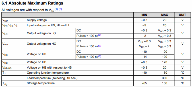
The gate driver does not have a current rating, on any pins actually:

enter image description here

If a parameter doesn't appear in the absolute maximum ratings table, don't worry about it.

Well... maybe. Such a principle may occasionally result in concerned calls to the manufacturer's FAE. But, in that case, whether a bug of documentation or actual chip design, it's at least their fault, not yours. Whether you want to plan for such oversights in a given project, or prefer a more conservative approach, is up to you.

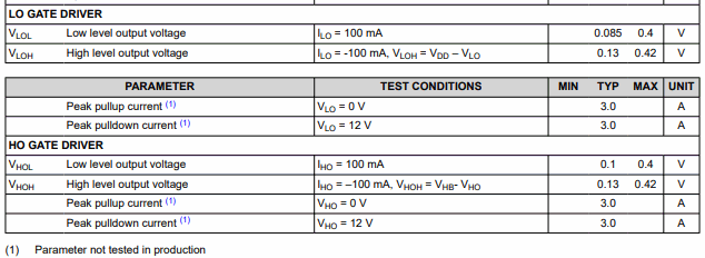
The current rating:

enter image description here

is the peak current it's capable of, at all. In this case, only the typical current at that, so, you don't really know how much a random sample will deliver, or under different conditions (in general, it depends on VCC and Tj). It's a characteristic -- what it's capable of, under given conditions; in this case, shorted to the opposite rail.

So, it's perfectly fine to run a gate circuit with zero external resistance, at least in the right circumstances.

It's just safer to use a resistor, partly to have the option of controlling speed, and partly because things can be poorly behaved, particularly when there's much distance between driver and transistor. Without a gate stopper resistor at the transistor, oscillations can occur on switching edges, even at several 100 MHz.

\$\endgroup\$

Your Answer

By clicking “Post Your Answer”, you agree to our terms of service and acknowledge you have read our privacy policy.

Not the answer you're looking for? Browse other questions tagged or ask your own question.