2
\$\begingroup\$

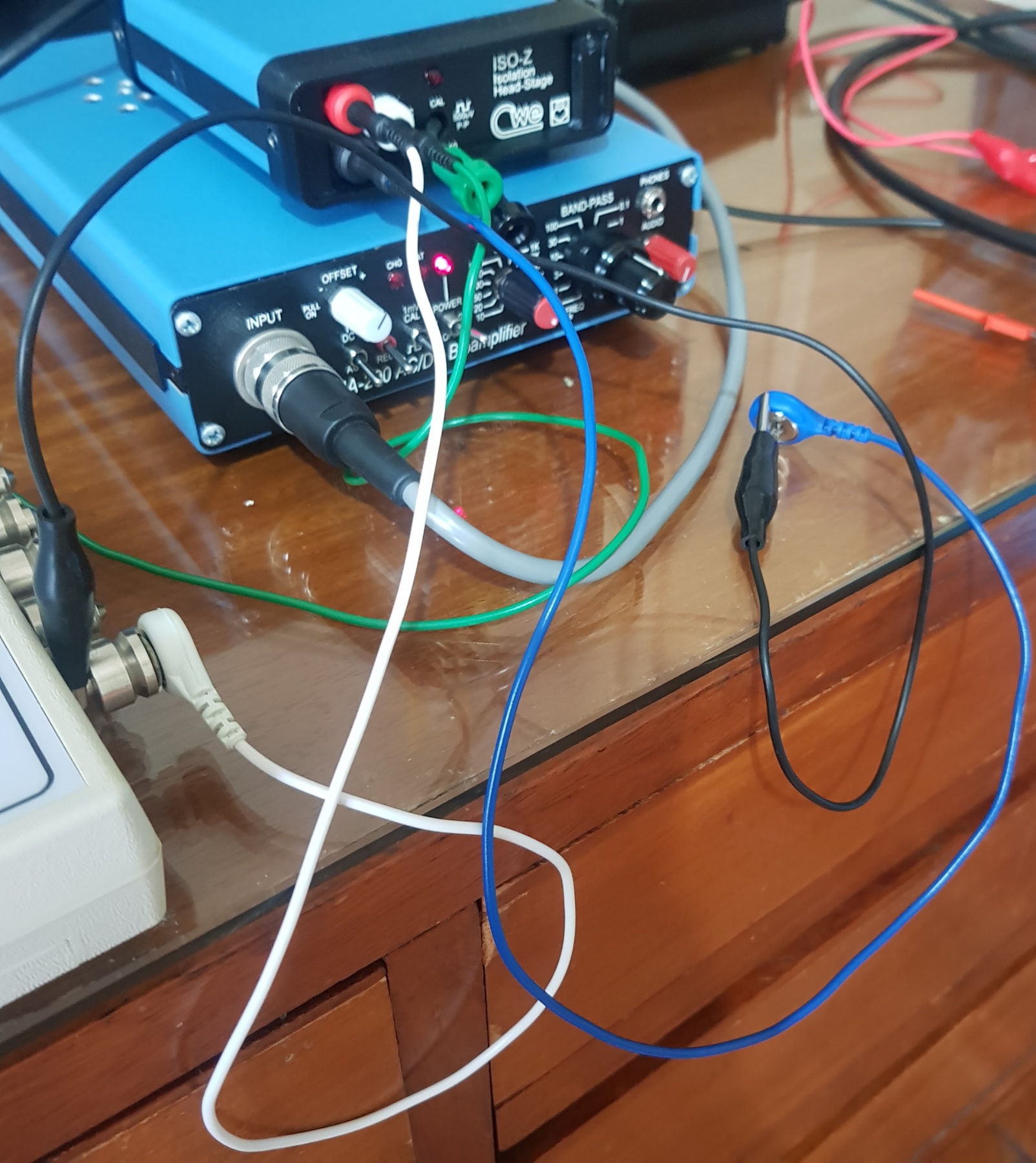
I used this equipment the BMA-200 with the AMP01 having a CMRR of 125dB.

enter image description here

I connected the signal generator output to both the In+ and In-. Yet the waveform still have retained sine wave of very small value (needing 50000X gain). Why? won't it be rejected as well? Is there a way to estimate what CMRR based on seeing retained sine wave?

enter image description here

To show the waveform at V+, i have to disconnect the V-. The output just need gain of 200 to display the original sine wave from signal generator.

enter image description here

\$\endgroup\$
6
  • \$\begingroup\$ I connected the signal generator output to both the In+ and In-. is this the only thing you've done to measure the CMRR? Can you show a schematic instead? I don't think this is a proper method to measure CMRR. \$\endgroup\$ Commented May 20 at 5:58
  • \$\begingroup\$ Im not measuring the CMRR. Just seeing if the same output going to In+ and In- of the equipmemt will get the signal cancelled. The picture shows it very clearly. But there is tiny sine wave retained..Why? \$\endgroup\$
    – Jtl
    Commented May 20 at 6:15
  • \$\begingroup\$ 1) What is your expected CMRR in dB. What is your measured CMRR in dB. There will always be some feedthrough - CMRR can't equal infinity. 2) When measuring effects in the ppm range such as this, every detail of the test setup matters. What is the phase shift between the two input signals. At some level of error, a phase shift between the 2 signals will be amplified - the correct interpretation of that error isn't a lower CMRR than expected. It can often take a good bit of time and work to isolate and either eliminate or quantify errors from sources other than the CMRR measure. \$\endgroup\$
    – JkingNH
    Commented May 20 at 6:34
  • \$\begingroup\$ The expected CMRR is 125. Im not measuring for CMRR. I just want to see how well can the common mode be rejected. The two input signal came from one output of the signal generator..How can phase shift occur? i hav tested other amplifiers, same retained tiny sine wave. for those who did similar tests. didnt u see any retained sine wave? \$\endgroup\$
    – Jtl
    Commented May 20 at 6:39
  • 1
    \$\begingroup\$ "I just want to see how well can the common mode be rejected" "Im not measuring for CMRR" -- then you will have to explain in precise detail what you are doing, because the standard means of "seeing" "how well" "common mode" can be "rejected" is the Common Mode Rejection Ratio. If you can provide a precise definition of what you are looking for, and how it differs from the definition of CMRR, that will greatly help us to answer your question. \$\endgroup\$ Commented May 20 at 7:55

1 Answer 1

4
\$\begingroup\$

I connected the signal generator output to both the In+ and In-. Yet the waveform still have retained sine wave of very small value (needing 50000X gain). Why? won't it be rejected as well?

Since no amplifier has perfect common mode rejection, there will not be perfect cancellation. You will get some signal at the output, though it may be very small. The ratio between the AC amplitude of this output signal to the AC amplitude of the input signal is the common mode gain.

Note that you are lucky that the amplifier didn't saturate when you applied the same signal to both In+ and In-. All amplifiers have offset voltage. That is, In+ and In- need to be slightly different to make the output 0. That difference is the input offset voltage. If you multiply the input offset voltage by the gain of the amplifier, you get the output offset voltage. For some amplifiers, the open-loop output offset voltage is greater than the voltage swing available in the opamp. In your case, that is apparently not the case.

Im not measuring the CMRR. Just seeing if the same output going to In+ and In- of the [equipment] will get the signal cancelled. The picture shows it very clearly. But there is tiny sine wave retained..Why?

The common mode rejection ratio is the ratio of the common mode gain to the differential mode gain. Your test showed the common mode gain, so to find the common mode rejection ratio, you must also find the differential mode gain. There are a number of ways of doing this. For an open-loop op-amp, you must first bring your input signal down to a level that is sufficiently small that it does not saturate your op-amp. This can be achieved by using a voltage-divider. Then apply this attenuated signal to one input, and hold the other signal at some reference point. A good reference point might be the mid-point between the voltage rails.

Once you have found the common mode rejection ratio, you may want to convert it into decibels (dB). To do so, take the base-10 logarithm of the ratio, and multiply that number by 20.

\$\endgroup\$
12
  • \$\begingroup\$ \$20\times log_{10} (2000) \approx 60\$. So if a CMRR of 2000 is about 60 dB. \$\endgroup\$ Commented May 20 at 13:57
  • \$\begingroup\$ I'm sorry, I wasn't thinking properly. The ratio between your output (with both inputs tied together) and your input is your common mode gain. Your common mode gain divided by your differential mode gain is your common mode rejection ratio. I will edit my answer. \$\endgroup\$ Commented May 20 at 23:28
  • \$\begingroup\$ my signal generator has 10uV, 30uV, 5uV, 1mV output..If all wont saturate the output. what must i choose. how do i know im getting the optimum differential mode gain? \$\endgroup\$
    – Jtl
    Commented May 21 at 0:19
  • \$\begingroup\$ Try 10uV, if the amplifier saturates, use a voltage divider, and try smaller signals until the amplifier doesn't saturate. \$\endgroup\$ Commented May 21 at 1:13
  • \$\begingroup\$ If I can get it to say 1uV. then the maximum gain is when further gain wont amplify it anymore? \$\endgroup\$
    – Jtl
    Commented May 21 at 1:31

Your Answer

By clicking “Post Your Answer”, you agree to our terms of service and acknowledge you have read our privacy policy.

Not the answer you're looking for? Browse other questions tagged or ask your own question.