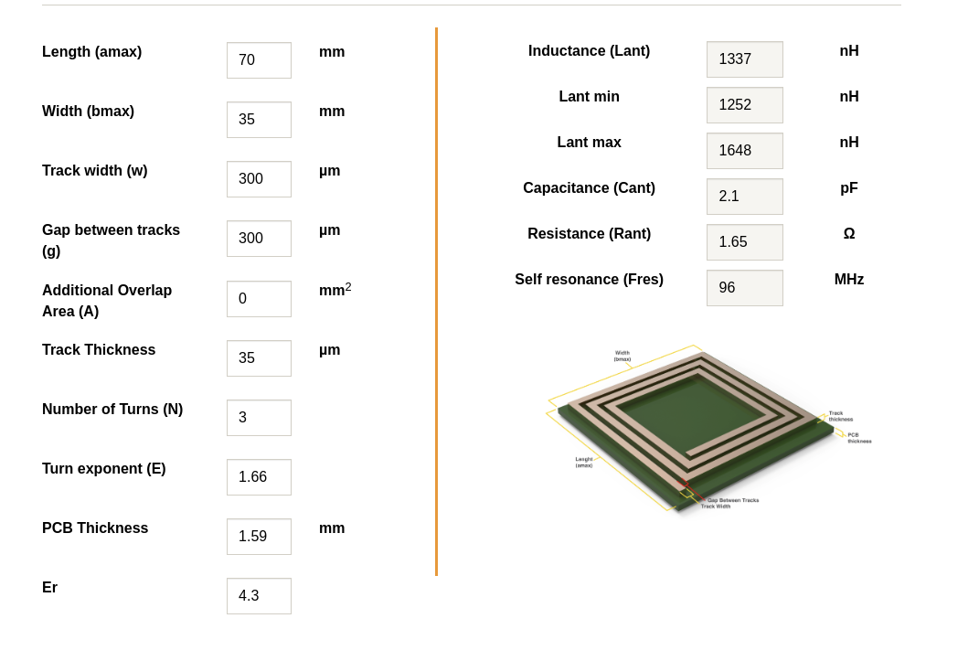
I am looking to design a custom RFID antenna which operates at 13.56 MHz. I have designed the antenna using the NFC Design tool (link). Please see the parameters below:
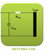
On top of that I ran some simulation in LTspice to compare the resonance frequency of the antenna circuit using "Antenna model" and successfully confirmed that the 96 MHz is correct.
This is the layout in Kicad PCB designer:
In the first go I was interested in only the antenna parameters thus the tuning circuitry falling left to the RF3 SMA header is detached (no R4 and R5 resistors placed).
Just received it from the manufacturer. In the meantime I took a hold of a NanoVNA device so that I can physically check the antenna parameters roughly. Calibration took place as required, also tested a 2.4 GHz standard antenna too to make sure the VNA is working properly and the the magnitude diagram showed a negative spike around 2.4 GHz, so it's ok.
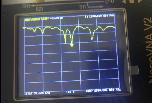
Finally I arrived to the point to connect the VNA to my custom antenna board, ANT_IN header. My expectation was to see a similar magnitude diagram similar to what I saw in my LTspice simulations. I did not see any negative spike at the theoretical resonance frequency (96 MHz) so I expanded the measurement range to what is going on:
It seems that the resonance freq. is a little above 1 GHz which is far off the desired ~100 MHz theoretical resonance freq. with another order of magnitude.
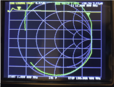
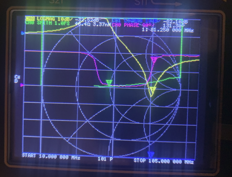
Figure 5: VNA measurements between 1-100 MHz
Unfortunately no resonance freq. here. Moving the cursor in the vicinity of 13.56 MHz the inductance value has proven to be ~2.11uH. This is apprx. half of the calculated value (1337 nH).
I cannot wrap my head around the fact what goes wrong honestly, but I must be making some mistake big time.
Please explain what I might be doing wrong.

