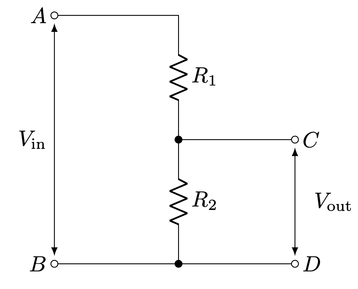
I'm trying to figure out how to calculate the Thevenin equivalent circuit for a voltage divider like the following one:
 I understand that V_th is obtained by opening the terminals of the output, so that V_out = V_in R2/(R1+R2). The problem is that I don't know how to calculate the current flowing into the output when generators are short circuited. The result should be I = V_in/R1, but the current after R1 will split in the current flowing into R2 and the current exiting the voltage divider, so this seems wrong to me. Can you help me understand why and how to calculate the I for the open circuit?
Thanks you a lot in advance for the help.
-
\$\begingroup\$ Take a look at this answer electronics.stackexchange.com/questions/377467/… Any additional qestions? \$\endgroup\$– G36Commented Jun 8 at 15:10
3 Answers
I understand that V_th is obtained by opening the terminals of the output, so that V_out = V_in R2/(R1+R2). The problem is that I don't know how to calculate the current flowing into the output when generators are short circuited. The result should be I = V_in/R1, but the current after R1 will split in the current flowing into R2 and the current exiting the voltage divider, so this seems wrong to me. Can you help me understand why and how to calculate the I for the open circuit?
Well, you expressed it pretty well. That's how you do it.
$$\begin{align*} V_{_\text{TH}}=V_{\text{open circuit}}&=V_{_\text{IN}}\frac{R_2}{R_1+R_2}\tag{voltage divider} \\\\ I_{\text{shorted circuit}}&=\frac{V_{_\text{IN}}}{R_1}\tag{shorted $R_2$} \end{align*}$$
If you divide the first by the second, then \$V_{_\text{IN}}\$ cancels out and the result is \$R_{_\text{TH}}=\frac{R_1\,R_2}{R_1+R_2}\$, which on the right side is the same expression for resistance that you get if you were to take the two resistors in-parallel to each other.
Since \$R_2\$ is bypassed by a short when working out the shorted circuit current, no current will occur in \$R_2\$ as the short (or wire) is infinitely less resistance. So there's nothing left over to go through \$R_2\$.
For me, what really made me understand this situation better wasn't by focusing entirely on the above approach. It's was too abstract.
What helped me more was by neither leaving the circuit open nor by shorting it, but instead by applying different resistors with finite values, in parallel to \$R_2\$. By experimenting with a few different values there, it really helped me a lot more to see better than before and to better appreciate the abstract approach (to "believe" more in it.)
So why don't you try picking values for \$R_1\$ and \$R_2\$ and then creating two or three values for a load resistance that you apply across \$R_2\$. Work out the results from that in terms of the voltage that the load experiences in these cases and compare it to what you would get using the simplified Thevenin circuit, with only one voltage source \$V_{_\text{TH}}\$, and one source resistance, \$R_{_\text{TH}}\$. It will all work out and it will help a little, I think. Try it.
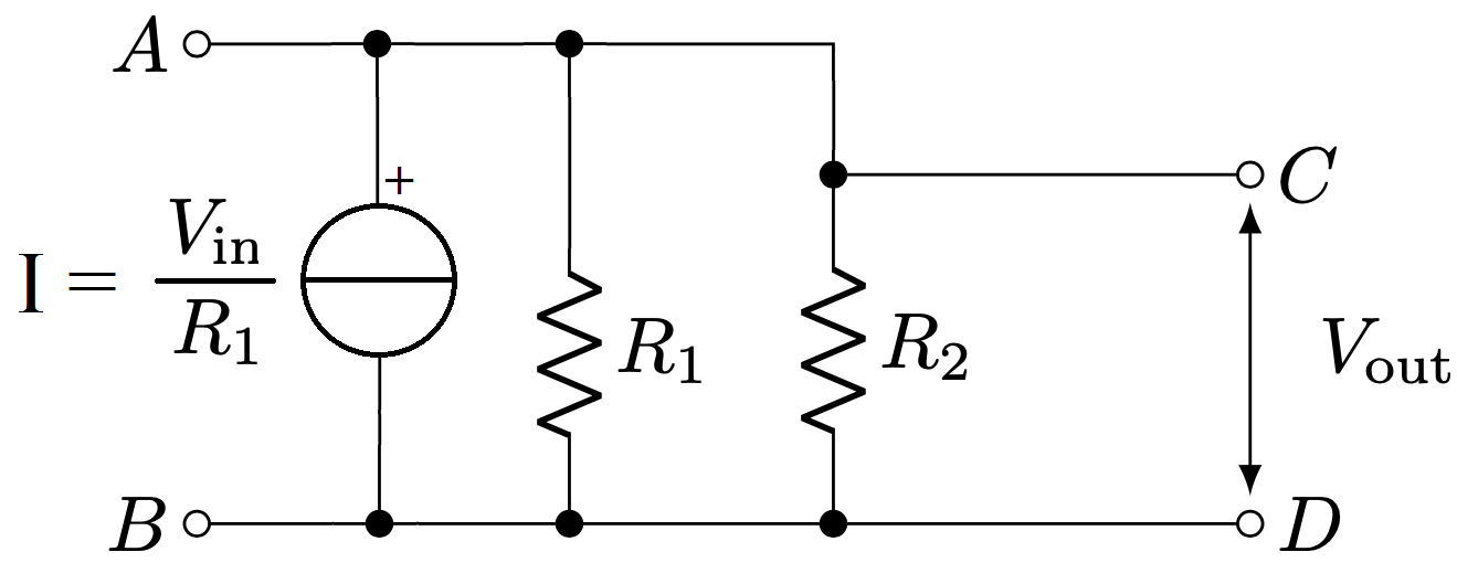
Just turn the voltage source (Vin) and R1 into a current source: -
Hence, the Thevenin resistance (as viewed from terminals C and D is R1 || R2.
It's called source transformation and is an important weapon in your armoury for problems like this.
-
\$\begingroup\$ How likely is it OP knows the Norton equivalent (what you drew) of the original circuit if they don't know how to find the Thevenin equivalent? They wouldn't know the current is \$V_{in}/R_1\$ without already knowing the answer to the question being asked. \$\endgroup\$ Commented Jun 8 at 15:49
-
\$\begingroup\$ Photon, it was a very long time ago but, I was taught source transformation before any other circuit theorem (other than ohm's law) so, if he wasn't taught that first I'm sure he'll let me know. \$\endgroup\$– Andy akaCommented Jun 8 at 16:00
The problem is that I don't know how to calculate the current flowing into the output when generators are short circuited. The result should be I = V_in/R1, but the current after R1 will split in the current flowing into R2 and the current exiting the voltage divider...
Just to be clear, to find the short circuit output current, you should be shorting the load (what's connected across Vout), not the generator (what's connected across Vin).
If the output is shorted, then you know the voltage across R2.
From that you know exactly how much current is flowing through R2.
If you know the current through R1, and the current through R2, then you (from KCL) know the current flowing through the load.
It may help to actually, on a piece of paper, re-draw the circuit with the source shown explicitly and the short circuit at the output drawn explicitly.
-
\$\begingroup\$ The op actually said this: I don't know how to calculate the current flowing into the output when generators are short circuited. You seem to assume he said when the output is shorted so I'm unsure where this is useful. I mean; it's likely a typo by the OP but, until he corrects that, it leaves your answer in limbo. \$\endgroup\$– Andy akaCommented Jun 8 at 17:11
-
1\$\begingroup\$ @Andyaka, when the generators are short-circuited, there's no current because there are no sources. So that's not an actual thing that OP should be doing to solve their problem. They also said "The result should be I = V_in/R1," which is not what you get when you short the source --- it's what you get when you short the load. \$\endgroup\$ Commented Jun 8 at 17:15
-
\$\begingroup\$ Yes I know that and that's why I avoided that route in my answer. \$\endgroup\$– Andy akaCommented Jun 8 at 17:16
-
1\$\begingroup\$ @Andyaka, I have updated the answer to clarify. \$\endgroup\$ Commented Jun 8 at 17:17

