0
\$\begingroup\$

This is my first time working on a PCB microcontroller board.

I'm working on a project that involves the control of several DC motors with encoders, and I've opted to make my own microcontroller board with integrated H bridge drivers using IRF540 N-channel MOSFETs. The maximum current draw for the motors which I want to use (FIT0185 DFROBOT) is 7 A, so I expect I'll only be drawing on average about 5 A. I'm using an ATmega2560-16AU as the brains.

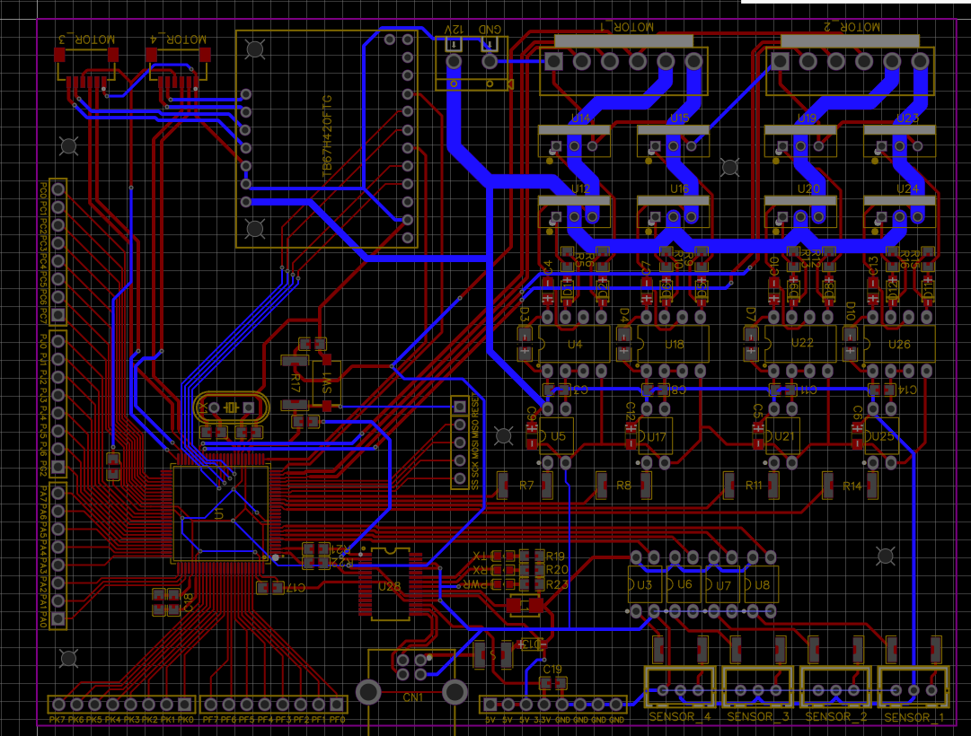
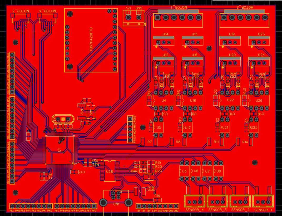
My question is whether the traces between the power supply connector, MOSFETs and motor connector are sufficiently wide, as I went with 2 mm width.

I calculated using Saturn PCB Design Toolkit, and for 7 A, the recommended trace width is about 3.5 mm, which seems way too big. When I calculated the amps that a 2 mm wide trace can withstand, it gave me around 5 A.

I'm thinking of setting the 2 mm traces as exposed copper and later adding solder to them. How much will this help? Or should I try to squeeze 3.5 mm traces?

enter image description here

enter image description here

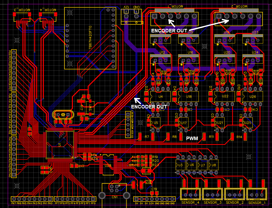
Also, I want to control the speed and position of these motors accurately, but I'm concerned that the trace lines from the MCU to the PWM inputs and from the encoder outputs to the MCU are way too lengthy and that the signals might be affected. I've marked them on the images below. Trace width for PWM in is 0.4 mm and for encoder out is 0.5 mm.

enter image description here

enter image description here

Thank you in advance!

EDIT

I'll add a link to the motors which I'll be using (https://www.tme.eu/ro/en/details/df-fit0185/dc-motors/dfrobot/fit0185/). I forgot to add that the operating current for these motors is 0.35A which is absolutely manageable, however the stall current is 7A.

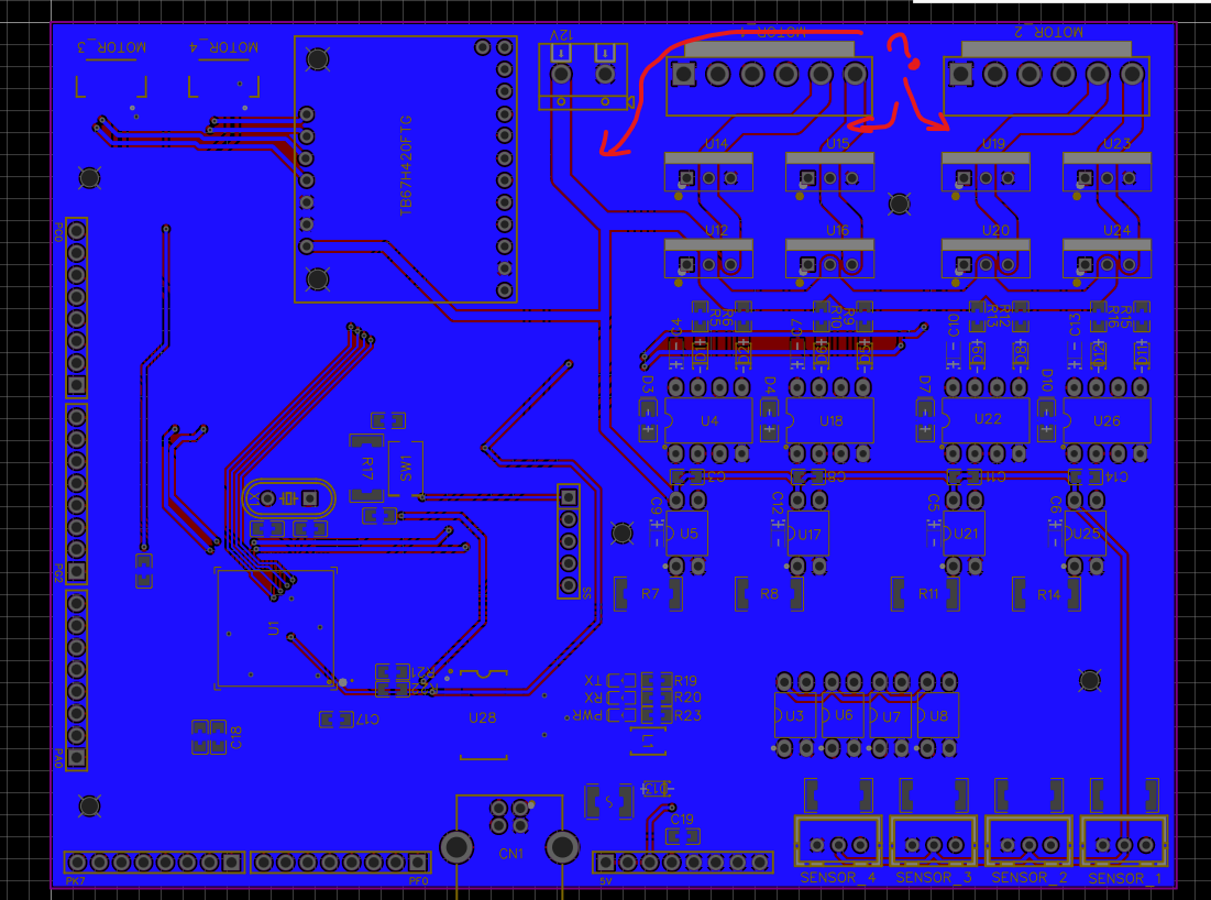
\$\endgroup\$
6
  • \$\begingroup\$ How much temperature rise and voltage drop can you accept? \$\endgroup\$
    – winny
    Commented Jul 3 at 10:07
  • \$\begingroup\$ Regardless of trace width, it might be a good idea to add some manner of heat sink to those TO220 MOSFETs. \$\endgroup\$
    – Lundin
    Commented Jul 3 at 11:14
  • \$\begingroup\$ Is pin 1 of the motor connectors the motor ground? Because then it will obviously need to be as beefy as the rest. \$\endgroup\$
    – Lundin
    Commented Jul 3 at 11:15
  • \$\begingroup\$ If you are stuck with 2 layers, I wound attempt to ground pour and use as many vias as possible to stitch them together around your traces which is breaking up your planes. \$\endgroup\$
    – winny
    Commented Jul 3 at 11:27
  • \$\begingroup\$ If you're concerned, don't forget that you can always go to thicker copper. While it gets pricy quick when you go with the really thick options, 2 oz/70 μm copper (which is double the normal thickness) is usually pretty affordable. \$\endgroup\$
    – Hearth
    Commented Jul 3 at 14:01

1 Answer 1

1
\$\begingroup\$

Using a standard IPC-2221 calculator, for 7A current and 1 oz/ft² copper thickness with a 10°C temperature rise:

Internal Layer: Approximately 7.4mm
External Layer: Approximately 2.4mm

Since you are using external layer, 2mm should do for a SINGLE motor trace. You will eventually get slightly more than +10°K tho. Make sure your board can dissipate that. So no tight enclosure or you need to incorporate active cooling. Maybe add some more PTHs for screwing it to a metal plate and dissipate heat that way.

For the suppy line towards the MOSFETS, you need to use a trace that can withstand the COMBINED motor current!

\$\endgroup\$
3
  • \$\begingroup\$ You also want to put a couple vias in the GND-plane to improve the current return path. \$\endgroup\$
    – S_G
    Commented Jul 3 at 10:17
  • \$\begingroup\$ It's a 2 layer board so no GND plane as such. Pic 1 is just solder mask, no copper pour. \$\endgroup\$
    – Lundin
    Commented Jul 3 at 11:16
  • \$\begingroup\$ I refer to every GND copper pour as a GND plane. just stitch them together and you have a sufficient "GND plane". Dedicated GND planes with zero signals in them are rather niche in my book. @Lundin \$\endgroup\$
    – S_G
    Commented Jul 3 at 11:19

Your Answer

By clicking “Post Your Answer”, you agree to our terms of service and acknowledge you have read our privacy policy.

Not the answer you're looking for? Browse other questions tagged or ask your own question.