1
\$\begingroup\$

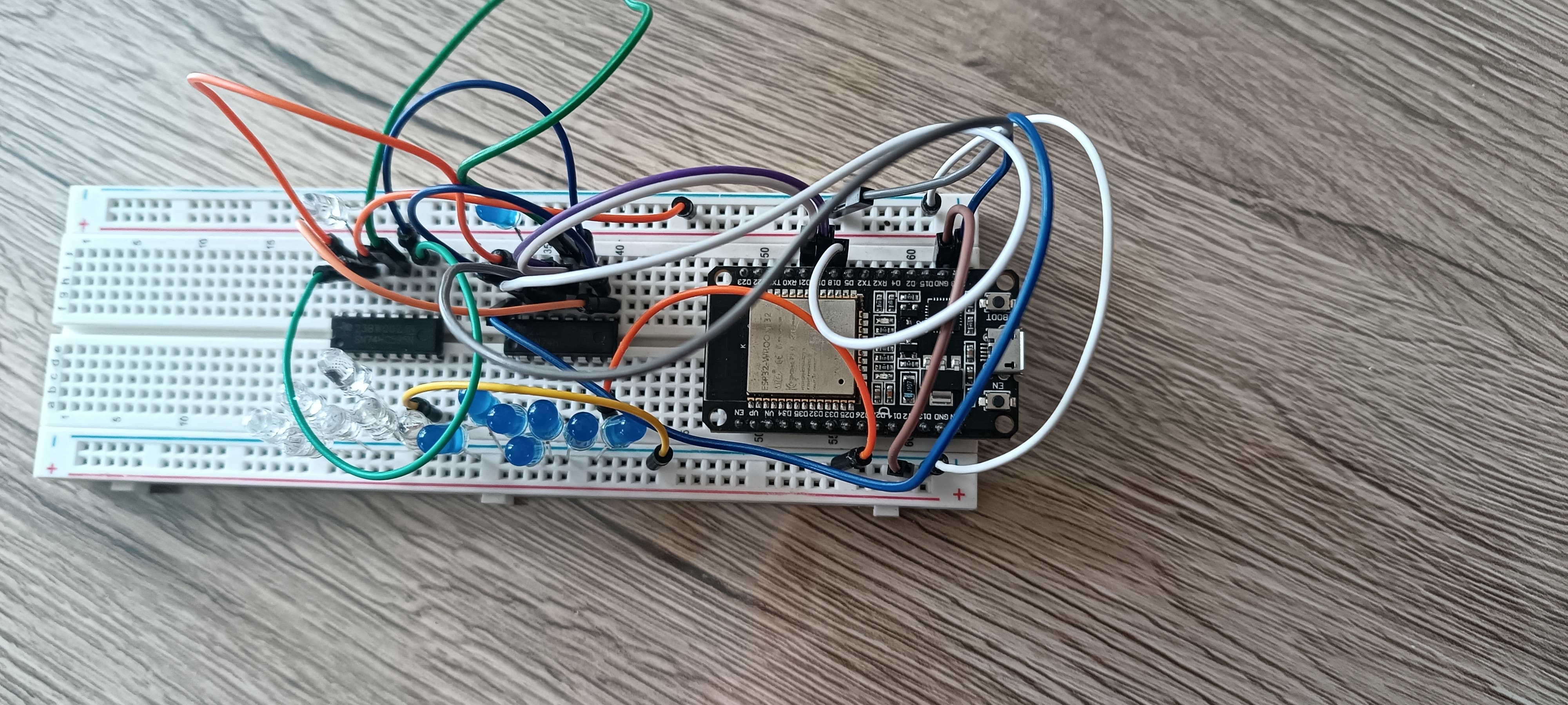
I'm trying to make a Nixie clock based on an ESP32. I've made a working prototype on a breadboard. Only the 74HC595 part, which is where the problem is at:

working prototype on breadboard

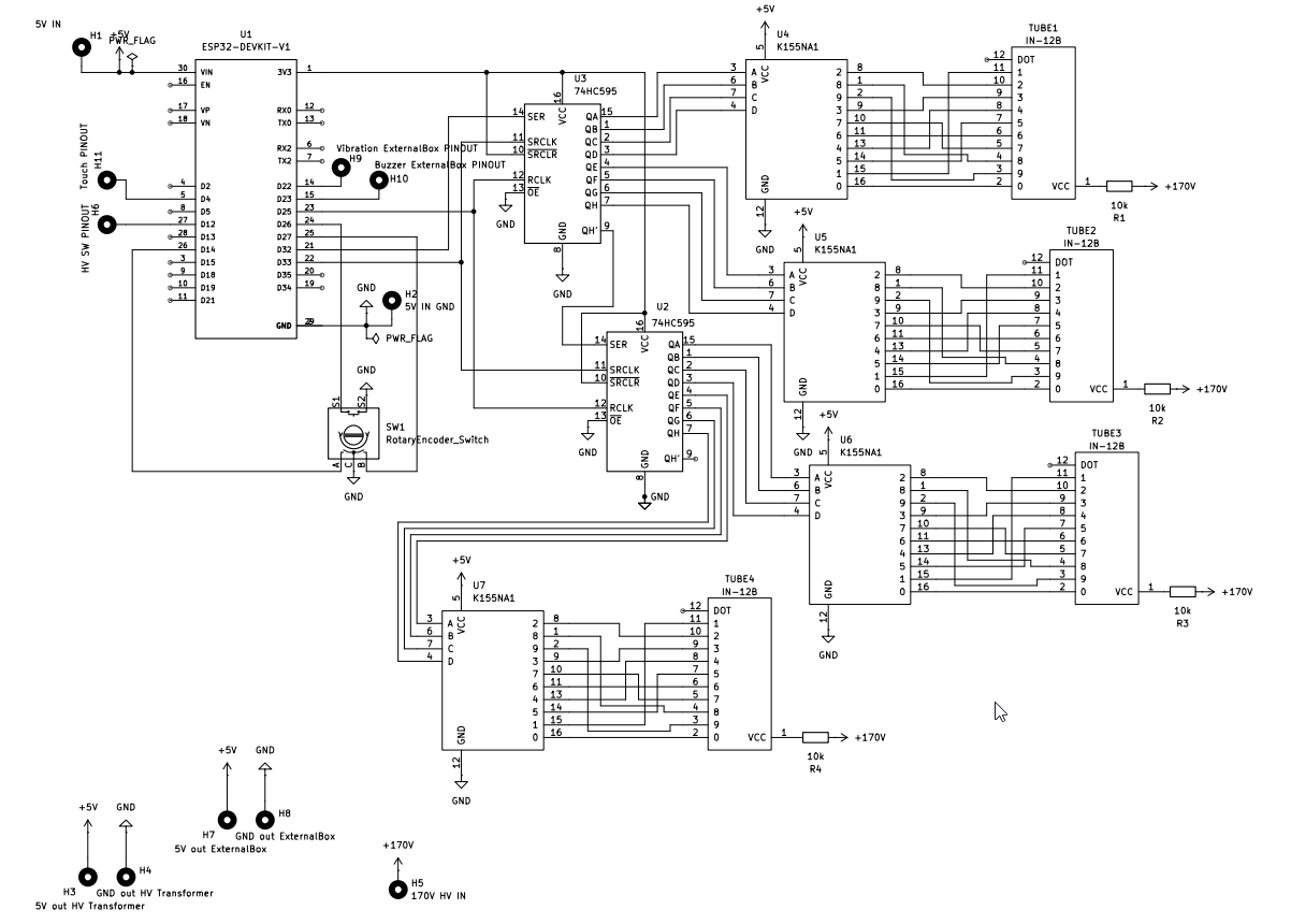
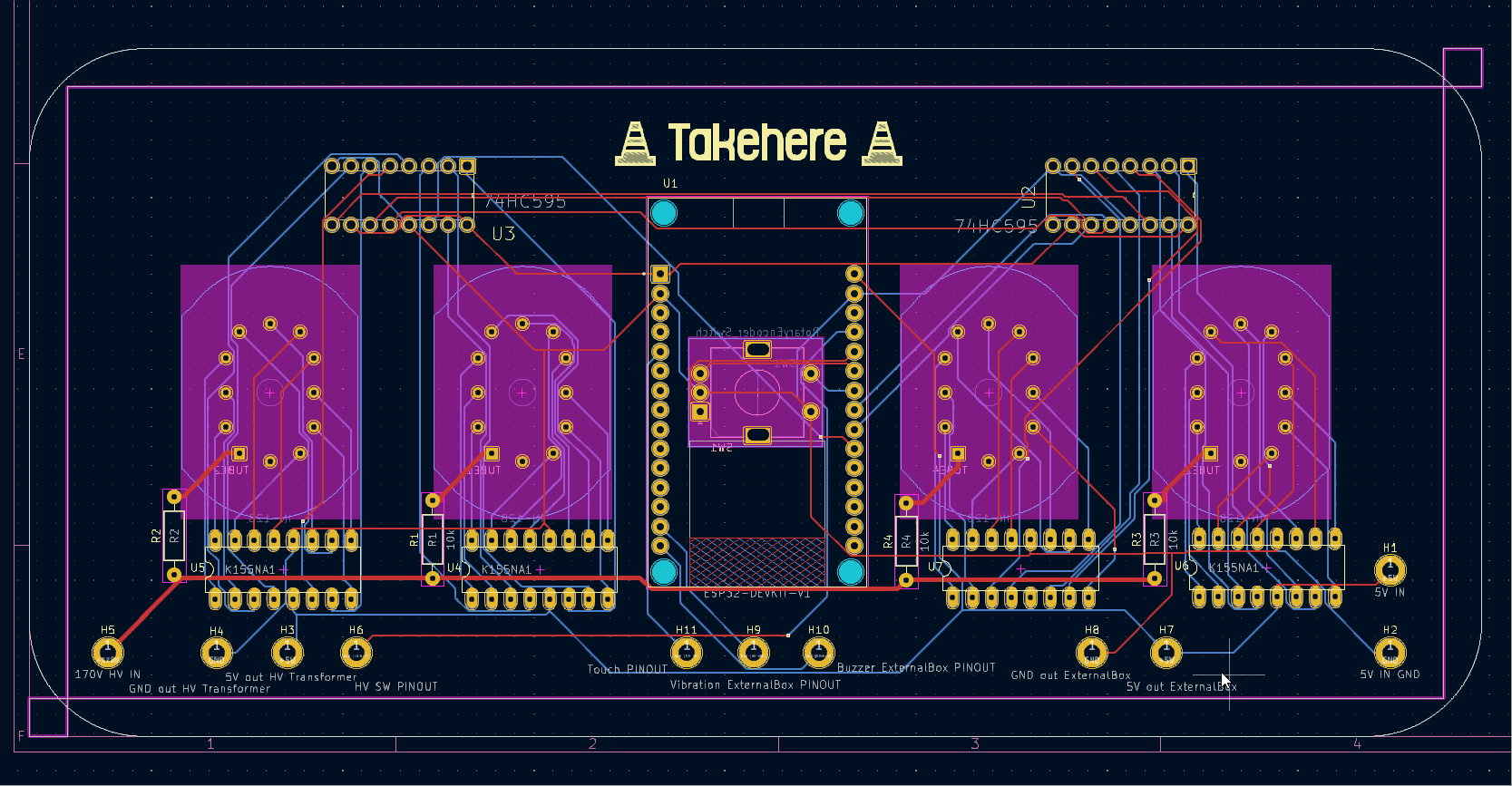
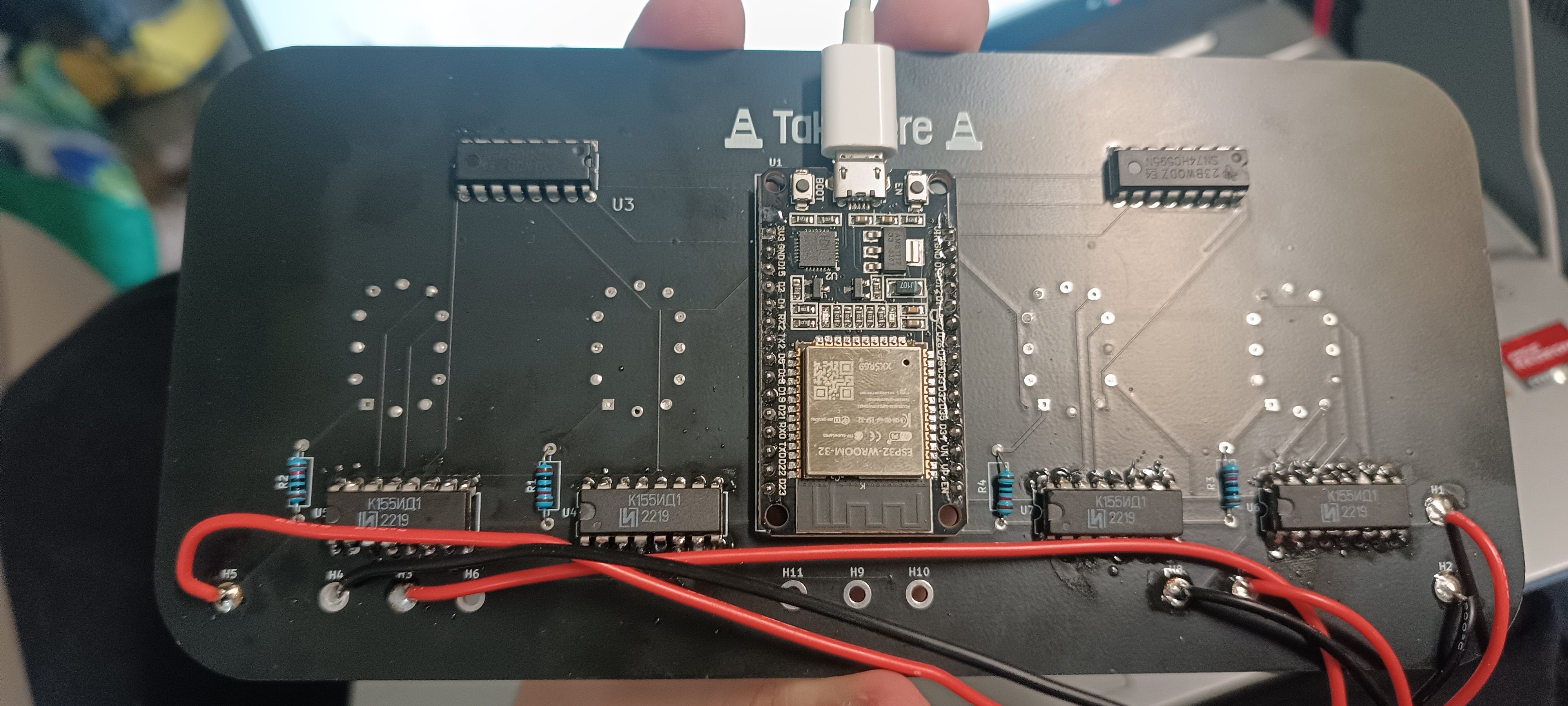
I then made a PCB:

pcb shematic traces

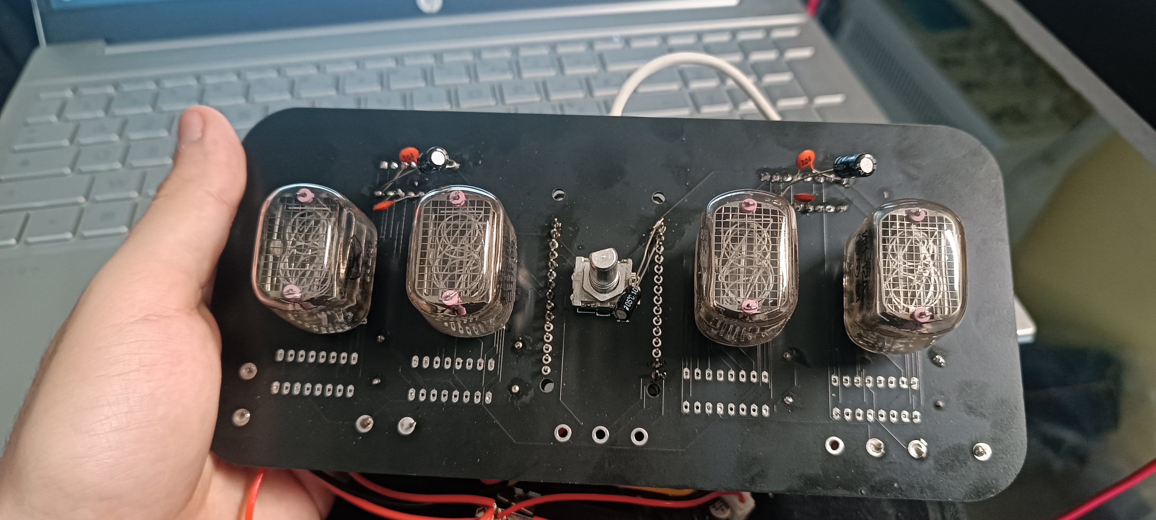
After soldering everything to it (I've verified every solder connection, it's all good,) the 74HC595 behaves randomly. Each time I start it, the output values are all random until it settles on a number. I have tried everything I saw on the internet but nothing works. I also tried adding a bunch of capacitors but it doesn't work either.

Here are the results after soldering:

enter image description here

enter image description here

How to troubleshoot this?

Here is the test code U'm using for both the working prototype and the PCB:

//uint8_t latchPin = 19;
//uint8_t clockPin = 21;
//uint8_t dataPin = 18;

uint8_t latchPin = 33;
uint8_t clockPin = 25;
uint8_t dataPin = 32;

const byte segments[10] = { // Lookup table for digit patterns (common cathode)
  0b11110000,  // 0
  0b00001111,  // 1
  0b11110000,  // 2
  0b00001111,  // 3
  0b11110000,  // 4
  0b00001111,  // 5
  0b11110000,  // 6
  0b00001111,  // 7
  0b11110000,  // 8
  0b00001111   // 9
};

void setup() {
  // Set control pins as outputs
  pinMode(latchPin, OUTPUT);
  pinMode(clockPin, OUTPUT);
  pinMode(dataPin, OUTPUT);

  Serial.begin(115200); // Start serial communication for debugging
  Serial.println("Starting...");

  displaySegments(0x00000000); // reset on startup, not needed just makes it look better ig
  delay(1000);
}


void loop() {
  // Loop through each digit pattern (modify for specific display)
  for (int i = 0; i < 10; i++) {
    shiftOutt(dataPin, clockPin, MSBFIRST, segments[i]);
    digitalWrite(latchPin, LOW); // Latch the data
    delay(2000);     // Short delay for visibility (adjust as needed)
    digitalWrite(latchPin, HIGH); // Unlatch for next data

    Serial.print("Displaying: ");
    Serial.println(segments[i]);
  }
}

void displaySegments(byte pattern) {
  shiftOutt(dataPin, clockPin, MSBFIRST, pattern);
  digitalWrite(latchPin, LOW);
  delayMicroseconds(1000); // no need to edit this
  digitalWrite(latchPin, HIGH);
}

void shiftOutt(uint8_t dataPin, uint8_t clockPin, uint8_t bitOrder, uint8_t val) // just in case
{
      uint8_t i;

      for (i = 0; i < 8; i++)  {
            if (bitOrder == LSBFIRST)
                  digitalWrite(dataPin, !!(val & (1 << i)));
            else
                  digitalWrite(dataPin, !!(val & (1 << (7 - i))));

            digitalWrite(clockPin, HIGH);
            digitalWrite(clockPin, LOW);
      }
}

EDIT: Thanks for all your answers ! I read them all and tried all of them, but it still behaves randomly. What i tried:

  • Added 104 (0.1 µF) ceramic capacitors between GND and VCC for both the 74HC595 and K155NA1
  • Added some delay between each clock pulse: delayMicroseconds(2000); digitalWrite(clockPin, HIGH); delayMicroseconds(2000); digitalWrite(clockPin, LOW);
  • Disconnected the power supplies of the K155NA1 and connected them to the 3V3 of the ESP32

Nothing has worked so far

\$\endgroup\$
12
  • 2
    \$\begingroup\$ Sounds like a power/ground issue to me. Where did you "add a bunch of capacitors"? \$\endgroup\$
    – vir
    Commented Jul 4 at 17:14
  • 2
    \$\begingroup\$ No decoupling capacitors ... \$\endgroup\$
    – Antonio51
    Commented Jul 4 at 17:37
  • 1
    \$\begingroup\$ @EdinFifić I do not think 74HC595 should have a 5V supply. The 3.3V control signals are less than specified minimum voltage for proper logic high for 5V supply. \$\endgroup\$
    – Justme
    Commented Jul 4 at 18:12
  • 1
    \$\begingroup\$ So, should I power the K155NA1 with 5v and put 3.3v in it's inputs from the ESP32 GPIOs ? \$\endgroup\$
    – TakeHere
    Commented Jul 4 at 20:15
  • 1
    \$\begingroup\$ How do you know for sure that 74HC595 is the only problem? Are you sure K155NA1 is not the problem as well? As has been pointed out by many others about 74HC595, I suggest using 74HCT595 (HCT version) chip if your are driving from ESP32, which can output max of 3.3V only. \$\endgroup\$
    – kaosad
    Commented Jul 5 at 3:24

4 Answers 4

2
\$\begingroup\$

Actually it's the other way around, I would not expect the breadboard prototype to work well either. The breadboard even connects LEDs directly to HC595 output pins which may lead to burnt-up LEDs or chips as there should be current limiting resistors.

There are no supply bypass caps on the IC power supply pins, and both implementations of the circuit uses long wiring between chips.

The only difference is, that when comparing the two, the PCB uses even thinner and longer wiring than the breadboard, so you have more problems with wiring inductance and less help from breadboard having lots of stray capacitance everywhere.

So basically the PCB has now most of the copper etched away on both sides and long narrow tracks are left behind while it should ideally be the opposite, most copper left present to carry a proper ground plane, preferably a large plane or wide tracks for supply current, and the data wiring on top of a ground plane to shield them.

The code itself should work, however with the actual PCB, the clock pulses for sending data may be too short and get distorted on the PCB and there may be reflections due to the PCB design not being very compatible with high speed design. Any series resistance on the clock pin and putting some delay to make clock pulse longer and letting the data pin stabilize before rising clock edge would be a nice addition.

\$\endgroup\$
3
  • \$\begingroup\$ As i said in my edit, i tried adding delay between clock pulses and it didn't change a thing. In addition, i would like to add that the protoype being a temporary thing, I didn't think it was necessary to use resistors, especially as I use resistors with a high tolerance to current (blue and white LEDs need a high current and are therefore more tolerant than yellow LEDs, for example, so they can be used temporarily without resistors). Could you also specify a bit more the idea of adding a resistance in series with the clock pin ? What value to use ? \$\endgroup\$
    – TakeHere
    Commented Jul 4 at 19:28
  • 2
    \$\begingroup\$ You really do need resistors for LEDs. The only reason nothing burned up was that they were blue/white LEDs, they generally require more than 3.3V what you supply so they could not pass damaging amounts. 5V would have burned something up, the chip damages after 35mA from IO pin and after 70mA from supply pin. Basically to be on safe side you have max 6..8mA per LED. Try about 100 ohms on the clock pin. \$\endgroup\$
    – Justme
    Commented Jul 4 at 20:02
  • \$\begingroup\$ @TakeHere The reason why resistors are added in series with digital or switching signals is because the parasitic inductances and capacitances of the wires and leads create "ringing" or oscillations during fast voltage/signal changes. Resistors serve to slow down the speed of voltage/signal change and thus reduce ringing, but they also absorb a portion of the ringing energy, giving a less noisy signal in the end. VALUES are typically from a few ohms and up to a 100 ohms. You could start with 10 ohms. \$\endgroup\$ Commented Jul 4 at 21:15
1
\$\begingroup\$

I would like to thank all of those who tried helping me troubleshoot this problem.

Unfortunately, none of the answers worked. I therefore used the remaining pins of the ESP32 to drive the K155NA1 instead of the 74HC595.

\$\endgroup\$
1
  • \$\begingroup\$ Apparently, D12 on ESP32 must be low during boot, see if that makes any difference (I'm not sure what it connects to and what it does in your circuit). \$\endgroup\$ Commented Jul 7 at 17:47
1
\$\begingroup\$

Each time I start it, the output values are all random until it settles on a number

It sounds like you are seeing the register powering up in an undefined state, which is normal. There's no guarantee that any of the register bits will be 1 or 0 after power is applied.

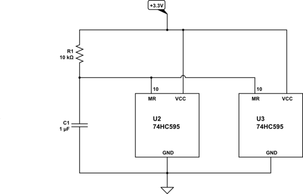
To ensure that the register is clear (all zeros), it's common practice to apply a short reset pulse at power-on, by holding \$\overline{MR}\$ low (pin 10, which your schematic has labelled SRCLR) using an RC delay:

schematic

simulate this circuit – Schematic created using CircuitLab

The values shown hold \$\overline{MR}\$ low for a few milliseconds, approximately \$\tau=R_1C_1\$, during which time all register bits are set to zero while the power supply settles.

Of course, any data operations on the register (by the microcontroller) that occur during this reset period will be ignored, so you must wait before you start shifting in data.

\$\endgroup\$
0
\$\begingroup\$

I see two possible issues here:

  1. You should have at least 100nF (0.1uF) capacitors between the positive supply pins of 74HC595 and K155NA1, and their GND pins. They shoud be as close as possible to those pins and their leads/connections should be as short as possible.

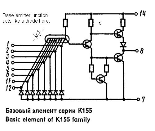
  2. Datasheet for 74HC595 mentions that its outputs should NOT be pulled up above its supply voltage, which is 3.3V, while K155NA1 is supplied by 5V and its inputs seem to leak currents from its positive, 5V supply.

K155 IC family datasheet found at https://www.digchip.com/datasheets/parts/datasheet/922/K155NA1-pdf.php : K155 IC family datasheet

Page 14 of 74HC595 datasheet from Texas Instruments (https://www.ti.com/lit/ds/symlink/sn74hc595.pdf) : enter image description here

\$\endgroup\$
3
  • 1
    \$\begingroup\$ The data sheet does say outputs should not be pulled above VCC supply. However it is a blanket staement copied recently to all data sheets. It is a good idea to not pull them above VCC, but the datasheet also says it is OK if you limit the current, and if the leakage is only around few hundred uA per pin, it should be fine. 3.3V CMOS outputs should be able to drive 5V TTL inputs just fine. \$\endgroup\$
    – Justme
    Commented Jul 4 at 18:08
  • \$\begingroup\$ I just tested adding capacitors as you said and changed the 5v input of the K155NA1 to 3v3 from the ESP32, sadly, it didn't change a thing. Could you also specify a bit more what you mean by "leaking current from it's supply " ? \$\endgroup\$
    – TakeHere
    Commented Jul 4 at 19:31
  • \$\begingroup\$ @TakeHere Just keep the suply voltages as specified in the schematic. It was worth a try. \$\endgroup\$ Commented Jul 4 at 21:18

Your Answer

By clicking “Post Your Answer”, you agree to our terms of service and acknowledge you have read our privacy policy.

Not the answer you're looking for? Browse other questions tagged or ask your own question.