2
\$\begingroup\$

I'm trying to derive the RC charging circuit equation for capacitor voltage \$V_C\$ and charging time \$t\$. Here's my solution,

We'll start by assuming the battery, resistor and capacitor are connected in series.

  • KVL states that sum of all voltages in series is zero. This gives us \$V_B+V_R+V_C=0\$.
  • KCL states that current is equal everywhere in a node. We only have a single node where everything is connected in series. This gives us \$I=I_C=I_R=I_B\$.

Substituting the values for \$I_C\$ and \$I_R\$ in KCL we get, \$C\frac{dV_C}{dt}=\frac{V_R}{R}\$ where \$V_C\$ is the voltage across the capacitor and \$V_R\$ is the voltage across the resistor. Although from KVL above, we know that \$V_R=-V_B-V_C\$ or \$V_R=-(V_B+V_C)\$ if we take minus common. Now, Substituting the value for \$V_R\$ in our previous equation we get, \$C\frac{dV_C}{dt}=\frac{-(V_B+V_C)}{R}\$. Rearranging this would yield, \$\frac{1}{V_B+V_C}dV_C=-\frac{1dt}{RC}\$. Taking integral on both sides now yields, \$log_e(V_B+V_C)=-\frac{t}{RC}\$.

Note this equation \$log_e(V_B+V_C)=-\frac{t}{RC}\$. I'll use this to derive time \$t\$.

Taking exponential on both sides yields, \$e^{log_e(V_B+V_C)}=e^{-\frac{t}{RC}}\$. This simplifies into, \$V_B+V_C=e^{-\frac{t}{RC}}\$ which upon rearranging yields, $$V_C=-V_B+e^{-\frac{t}{RC}}$$.

Solving for initial condition's where \$t=0\$ and \$V_C=V_{C0}\$ in our solution above gives us \$V_{C0}=-V_B+e^{-\frac{0}{RC}}\$. This simplifies to, \$V_{C0}=-V_B+e^0\$ and then \$V_{C0}=-V_B+1\$. Putting \$V_B\$ on the left hand side yields, \$V_B=-V_{C0}+1\$. Now If I substitute \$V_B\$ into the equation above \$V_C=-(-V_{C0}+1)+e^{-\frac{t}{RC}}\$. Rearranging this yields, $$V_C=V_{C0}+(e^{-\frac{t}{RC}}-1)$$

However the standard equation is \$V_C=V_B(1-e^{-\frac{t}{RC}})\$ and I'm not sure what I did wrong.

Now deriving time from \$log_e(V_B+V_C)=-\frac{t}{RC}\$. We can arrange this to have \$t\$ on the left hand side, this results in \$-t=RC*log_e(V_B+V_C)\$. Multiplying \$-1\$ on both sides yields \$t=-1*RC*log_e(V_B+V_C)\$. We know \$-1*log(x)=log(\frac{1}{x})\$. Therefore our solution for time \$t\$ becomes $$t=RC*log_e(\frac{1}{V_B+V_C})$$.

However the standard equation for time is \$t=RC*log_e(\frac{V_B}{V_B+V_C})\$ and I'm not sure where I went wrong.

update: clarifying integral

This is how I solved the integral \$C\frac{dV_C}{dt}=\frac{-(V_B+V_C)}{R}\$.

  1. We can divide by \$(V_B+V_C)\$ on both sides. This results in, \$C\frac{dV_C}{(V_B+V_C)dt}=\frac{-1}{R}\$.
  2. We can multiply by \$dt\$ on both sides. This results in, \$C\frac{dV_C}{(V_B+V_C)}=\frac{-1}{R}*dt\$.
  3. We can divide by \$C\$ on both sides. This results in, \$\frac{dV_C}{(V_B+V_C)}=\frac{-1}{RC}*dt\$.
  4. Now we can take the integral on both sides, \$\int\frac{dV_C}{(V_B+V_C)}=\int\frac{-1}{RC}*dt\$.
  5. On the left hand side we have \$\int\frac{1}{V_B+V_C}dV_C\$. We know \$\frac{1}{x}=log_e(x)\$, therefore our left hand solution becomes \$log_{e}(V_B+V_C)\$.
  6. On the right hand side we have \$\int\frac{-1}{RC}dt\$. \$\frac{-1}{RC}\$ is constant so we can pull it outside and thus our right hand integral becomes \$\frac{-1}{RC}\int1dt\$. This simply results in, \$\frac{-1}{RC}*t\$ and then \$\frac{-t}{RC}\$.
  7. Combining left hand side and right hand side solutions from step 5 and step 6, we end up with \$log_{e}(V_B+V_C)=\frac{-t}{RC}\$

Is this wrong?

\$\endgroup\$
3
  • \$\begingroup\$ I think the KVL should be \$V_B-(V_R+V_C) = 0\$ \$\endgroup\$
    – Andy aka
    Commented Jul 5 at 15:43
  • \$\begingroup\$ The question then becomes why? KVL only states that "sum of voltages for all elements in a loop must be zero". In my perspective, I should've arrived to same solution regardless of polarity assumption because if "sum of voltages equals zero by KVL", it automatically implies that everything should cancel out anyway. \$\endgroup\$
    – Ayush
    Commented Jul 5 at 16:12
  • 2
    \$\begingroup\$ VR and VC are the opposite polarity to VB. \$\endgroup\$
    – Andy aka
    Commented Jul 5 at 17:22

3 Answers 3

2
\$\begingroup\$

KVL states that sum of all voltages in series is zero.

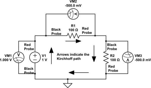
There is a constraint: The voltages of each element must be measured with the same orientation. The diagram aligns the voltages with the direction of the Kirchhoff path. They can be aligned opposite, but must be consistent.

Some consider voltage sources as positive with the passive element voltages as negative. So $$+V_1-V_{R1}-V_{R2}=0$$

schematic

simulate this circuit – Schematic created using CircuitLab

KCL states that current is equal everywhere in a node.

This is not right. KCL is:

"The sum of the currents into a node equals zero."

We only have a single node where everything is connected in series.

This also is not right. A series circuit of three elements has three nodes with two branches for each node.

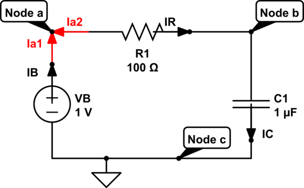
KCL must be applied twice to each of node a and node b showing the the element currents are equal.

For example at node a, $$ I_{a1}+I_{a2}=0 $$ Substituting element currents $$ I_{B}-I_{R}=0 $$ showing that $$ I_{B}=I_{R} $$

This is quite pedantic, so recognizing that elements in series must have the same current is much easier.

schematic

simulate this circuit

Your analysis:

Substituting the values for \$I_C\$ and \$I_R\$ in KCL we get, \$C\frac{dV}C{dt}=\frac{V_R}{R}\$

This is correct.

from KVL above, we know that \$V_R=-V_B-V_C\$ or \$V_R=-(V_B+V_C)\$

Here is the first error. It should be \$V_R=V_B-V_C\$

The differential equation should look like this:

$$ RC\frac{dv_C}{dt}+(v_C-v_B)=0 $$

So this is the second error. A change of variable must be introduced. You are attempting this but need to be careful. Also be clear that the shape of \$v_B\$ must be known. In this case it is a step of amplitude \$V_B\$, which is a constant for \$t\ge 0\$. So let \$x=(v_C-V_B)\$. Then $$ RC\frac{dx}{dt}+x=0 $$

The solution to this is $$ x=X_I e^{\frac{-t}{RC}} $$ where \$X_I\$ is the initial value of x.

Back substituting: $$ (v_C-V_B)=-V_Be^{\frac{-t}{RC}} $$

You should be able to take it from here. When solving problems of this type be certain to perform change of variable correctly.

\$\endgroup\$
1
  • 2
    \$\begingroup\$ Thank you Russel! That makes sense. \$\endgroup\$
    – Ayush
    Commented Jul 5 at 19:22
3
\$\begingroup\$

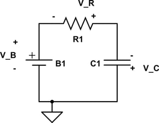
The main thing is you lost track of the polarity of your voltages. A diagram can be very helpful in keeping track of this. From your first point about KVL — \$V_B + V_R + V_C = 0\$ — you have:

schematic

simulate this circuit – Schematic created using CircuitLab

Obviously, at least one of the voltages needs to be negative in order for that to work. The "standard equation" assumes that the polarities of the resistor and capacitor are reversed from this. In other words, they simply write \$V_B = V_R + V_C\$ and go from there.

Also, your integration step is wrong. You're integrating with respect to \$t\$, but you ended up losing track of the \$dV_C\$ somewhere along the way.

\$\endgroup\$
3
  • \$\begingroup\$ I thought about the polarity of voltages when I first solved it. KVL only states that "sum of voltages in series must equal zero within a loop". It doesn't say anything about signs and polarity so I'm not sure why we need to take signs into account here. I think I should've still arrived on the solution if I solved with \$V_B+V_C+V_R=0\$. I also updated the question (at the bottom) and I clarified how I solved the integral and how I got \$log_{e}(V_B+V_C)=\frac{-t}{RC}\$. \$\endgroup\$
    – Ayush
    Commented Jul 5 at 15:34
  • 1
    \$\begingroup\$ Voltage is a signed quantity, so you definitely do need to keep track of polarity. And you can't just "throw away" the \$dV_C\$ when you're doing the integral. \$\endgroup\$
    – Dave Tweed
    Commented Jul 5 at 15:51
  • 1
    \$\begingroup\$ @Ayush Important : You can use any consistent sign convention that you wish BUT you have to have one AND if it produces signs different than what intuition suggests you still have to use what suits the convention. eg You cannot swap polarities just because it is convenient to do so. \$\endgroup\$
    – Russell McMahon
    Commented Jul 6 at 8:07
0
\$\begingroup\$

The error is introduced in the integration, because the resulting equation has voltage unit on left side and no unit on right side.

\$\endgroup\$
1
  • \$\begingroup\$ I updated the question (at the bottom) and I clarified how I solved the integral and how I got \$log_{e}(V_B+V_C)=\frac{-t}{RC}\$. \$\endgroup\$
    – Ayush
    Commented Jul 5 at 15:35

Your Answer

By clicking “Post Your Answer”, you agree to our terms of service and acknowledge you have read our privacy policy.

Not the answer you're looking for? Browse other questions tagged or ask your own question.