0
\$\begingroup\$

This is a setup with an ESP32-C3 and HX711.

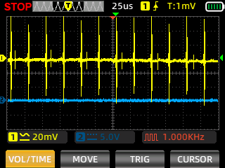
In this oscilloscope reading, there is a 10 μF cap and a 0.1 μF cap across the VCC and GND of the HX711 (it makes the load cell readings more stable).

Waveform with capacitors

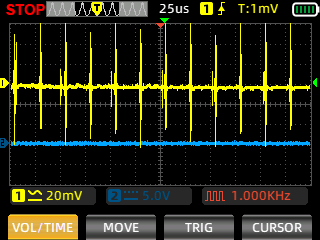
In this other oscilloscope reading, I have the same setup but without the 10 μF cap and a 0.1 μF cap (the load cell readings are more unstable).

Waveform without capacitors

How come the noise looks almost the same? I thought the caps were filtering out the noise or something.

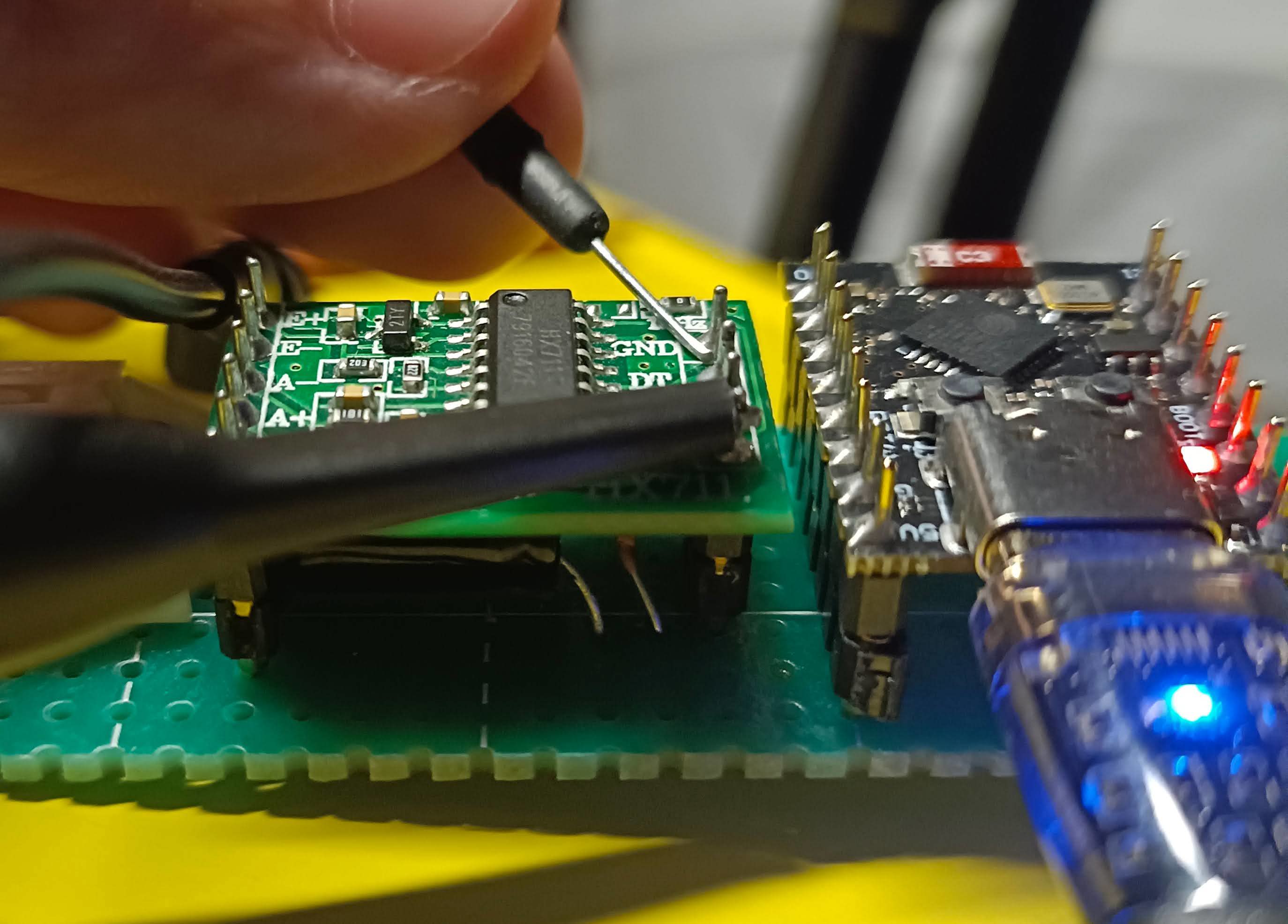
Note: I connected the oscilloscope probe to the VCC and GND of the HX711.

Photo showing pins under test

\$\endgroup\$
3
  • 1
    \$\begingroup\$ measurement question: how close to the contacts of your capacitors are your ground and + probe connections? And: what's the impedance of your probe's ground path? \$\endgroup\$ Commented Jul 15 at 14:01
  • \$\begingroup\$ @MarcusMüller The probes are attached to the top of the HX711, and the capacitors are right under the HX711. Like so: i.sstatic.net/IYcgN8xW.jpg. Sorry, how do I figure out what's the impedance of my probe's ground path? \$\endgroup\$
    – wyc
    Commented Jul 15 at 14:11
  • 1
    \$\begingroup\$ If you want an experimental setup to measure these: you'd excite a high-quality capacitor with known frequency dependency with a varying-frequency AC wave and look when you see resonance :) Usually, you'd use a probe where the ground connector is connected with a small spring right next to the positive side of the probe. You're measuring > 40 MHz, so chances are that the loop formed by the separate ground cable itself is picking up signal, or is hindering return current from the scope. \$\endgroup\$ Commented Jul 15 at 14:14

2 Answers 2

11
\$\begingroup\$

The way you probe the supply rail is not the preferred way because the probe and the ground clip form a large enough loop to pick up noise, quite possibly the noise you see on the scope display.

Try the following way:

enter image description here

Details and image source here.

\$\endgroup\$
8
  • 1
    \$\begingroup\$ Nice, +1! couldn't have written or illustrated it better; it's also a valid question whether ~10 mVpp noise at ~ 40 MHz is relevant to anyothing that is built like that! \$\endgroup\$ Commented Jul 15 at 14:16
  • 1
    \$\begingroup\$ moved OP's measurement setup to the question (your answer builds up on it, but I think it belongs in the question) \$\endgroup\$ Commented Jul 15 at 14:17
  • \$\begingroup\$ @wyc The probe's plastic rectractable part (the part the hook is attached) is removable. \$\endgroup\$ Commented Jul 15 at 14:36
  • \$\begingroup\$ Okay, thanks. I figured out how to remove the "hood" of the probe. So what should I use as the coil of wire. Any single-core wire? \$\endgroup\$
    – wyc
    Commented Jul 15 at 14:38
  • \$\begingroup\$ @wyc yes, any good conductor wire would work. Wrap around the metal sleeve as shown in the illustration, make sure the wire and the sleeve make a good contact. I use nickel rework wire as it's solderable, so I solder one end of the "coil" to the gnd-connection of the capacitor and leave it there for further probing when necessary. \$\endgroup\$ Commented Jul 15 at 14:40
2
\$\begingroup\$

As explained by Rohat Kılıç you need to use the proper measurement technique with the tiny ground clip, otherwise there is no way to know if the scope displays what you think you're measuring, or induction from nearby magnetic fields from your MCU into the large loop formed by the ground alligator wire.

When in doubt, always probe ground. I mean the only thing you change in your setup is to move the tip of the probe to the exact point on the PCB where the probe's ground clip or spring makes contact. Then you should see a flat line on the scope. If you do not see a flat line, or even worse if you see exactly the same trace on screen as before, then what the scope is displaying is definitely not noise on your power supply voltage.

The frequency of the noise spikes, about 40kHz, also feels like they come from a noisy USB wall wart/power supply. So if you do the above test and still see these spikes, then you can loop the probe's alligator ground clip to the probe tip, and now you have a loop antenna. Well, you already had a loop antenna, it comes for free with the ground wire, but at least now it's a useful tool instead of just being an annoying source of noise! You can move it around, and maybe you will get the same spikes when simply holding it near the 5V switching power supply or USB cables. If this is the issue, and your switching supply simply sprays its switching frequency everywhere, then it will be difficult to measure anything in the vicinity.

If you probe ground as explained above with the tiny ground spring on the probe, and you still get noise, then suspect a common mode noise issue, again probably the supply.

Regarding the importance of noise on your ADC measurements, let's check HX711 datasheet:
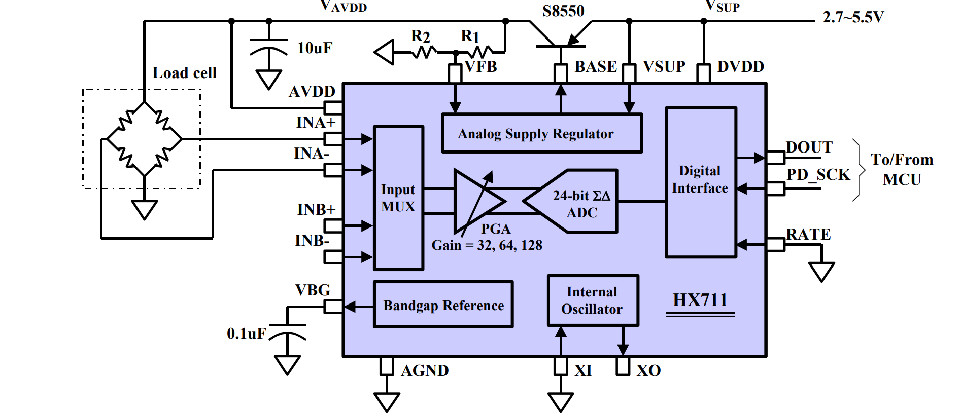
enter image description here

First things first: noise can only influence the ADC when it is doing a conversion. When the ADC isn't doing anything, then it won't care about noise. There is no way to know from the scope shot whether the noise spikes occur when the ADC is working, or when it is not working.

The ADC has several analog inputs: the signal inputs (labeled INA+/- etc) and the reference input. What an ADC actually does is compute the ratio between input voltage and reference voltage. Noise on both of these matters for the final result. So if you're interested in the ADC's supply voltage noise, you should be measuring AVDD which is your ADC reference, not DVDD which is only used for digital IO and the input of the chip's AVDD regulator.

That is of course assuming the module manufacturer didn't "cost-optimize" the AVDD regulator, but I see a SOT23 transistor and a bunch of ceramic caps on your photo, so it should be there.

Another way to get noisy measurements is a noisy signal. This can occur if wires are long, and they pick up noise from the MCU. If this is the case you can add filtering on the input, for example common mode and differential filtering caps.

\$\endgroup\$

Your Answer

By clicking “Post Your Answer”, you agree to our terms of service and acknowledge you have read our privacy policy.

Not the answer you're looking for? Browse other questions tagged or ask your own question.