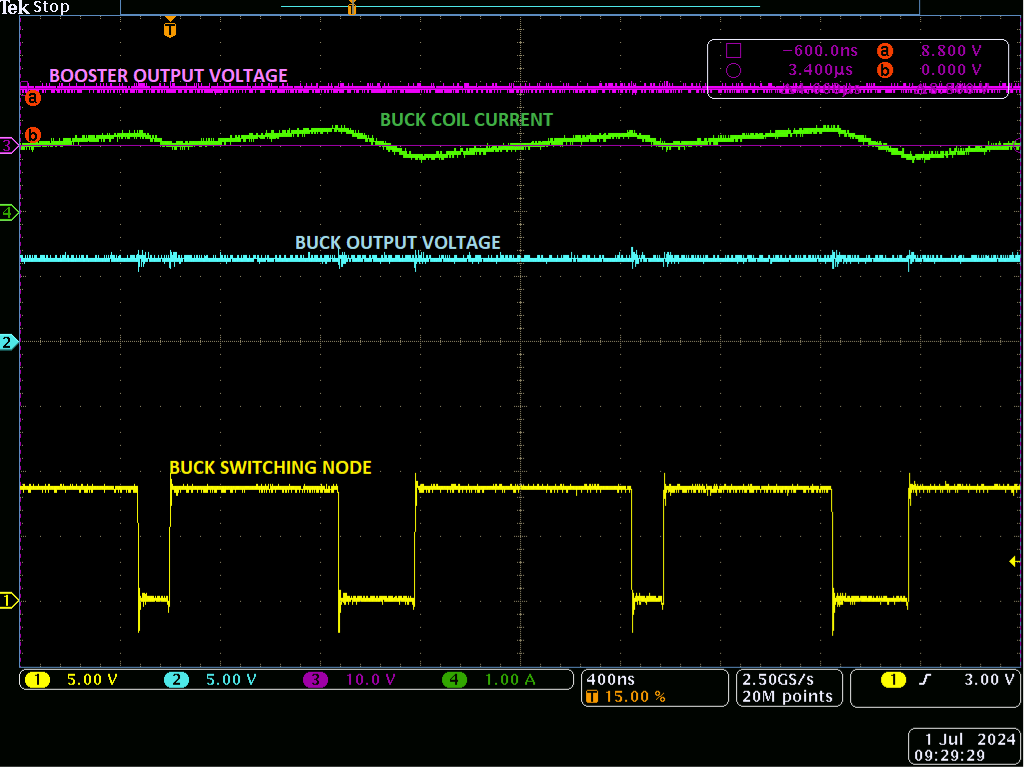
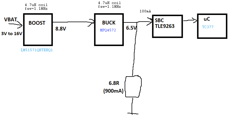
I am testing a BUCK converter and observed that has a variable DC when supplied at input voltages lower than 9.5V (if input voltage is higher than 9.5V the BOOSTER stops and DC is constant). The BUCK runs in CCM (not DCM)and this shall not happen. Can you please share your thoughts on what it could be causing this? I changed to a 10uH coil for BUCK and the DC is constant for the entire input voltage range 3V to 16V. See attached block diagram of the system. Thank you!
-
1\$\begingroup\$ I can't see anything in the figure. Could you crop it down to show the contents? \$\endgroup\$– Tim WilliamsCommented Jul 16 at 8:24
-
\$\begingroup\$ Hi Tim! Hope you can see the content now \$\endgroup\$– Florin AdrianCommented Jul 16 at 9:02
-
\$\begingroup\$ it would probably be good to add a schematic, and slightly more information - what do you mean by variable DC? Does it vary periodically, or with the input voltage? What amount does it vary by? Does varying the load make the output vary? \$\endgroup\$– BeB00Commented Jul 16 at 9:16
-
\$\begingroup\$ I would expect to have a constant DC for a constant load. Standard load of the buck is the SBC that supplies the uC (SBC is a power management IC that has 3 built in ldos to supply the internal circuits. VCC1 ldo is the main supply for uC). I checked with a current probe what is the average current in the coil when having the Standard load connected (sbc -> uC) and saw there is 100mA. Due to this low current the buck converter runs in DCM. I added an additional 6.8Ohm load to increase the current to have the buck run in CCM. When I do that below 9.5V input voltage the BOSSTER kicks \$\endgroup\$– Florin AdrianCommented Jul 16 at 9:28
-
\$\begingroup\$ Can you rephrase your first sentence? "variable DC" is that input or output? "Input voltage" is that input behind your boost or input to the buck after the boost? Have you considered a buck-boost instead of separate boost+buck? \$\endgroup\$– winnyCommented Jul 16 at 9:29
1 Answer
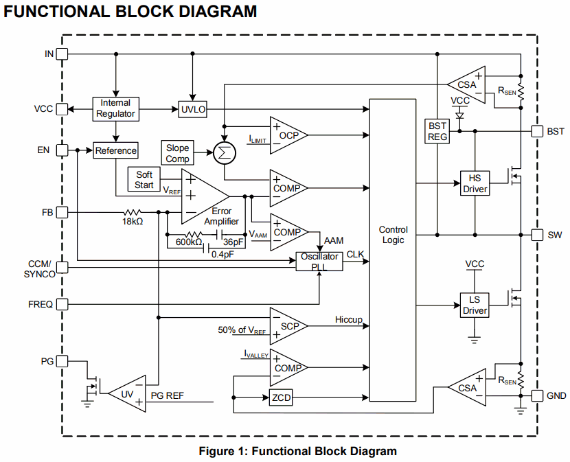
As we see from the block diagram,
Source: MPQ4572 Datasheet
It is a synchronous buck regulator with high-side current sense, current comparator, and slope compensation.
For some reason, the datasheet makes no hint about subharmonic oscillation, chaotic instability, when it's applicable, or how to choose L to avoid it. See SNVA555 Understanding and Applying Current-Mode Control Theory | Texas Instruments for example. (Note that the entire article strictly concerns CCM; DCM is completely inapplicable and any duty cycle and voltage ratio is acceptable in that mode.) They also give examples well into the unstable region; it almost seems like they intend this operation. On the other hand, all test data were measured well outside the region (24V in, 5V out), and also at lower frequency, though it seems still in moderately-deep CCM.
It's generally a good idea to stay on the high side of ripple fraction, i.e. use a relatively small inductor, so that CCM isn't too deep, and slope compensation can do its job. Subharmonic oscillation activates for Vin/Vout < 2, and worsens as ripple fraction goes below say 30%. The consequences are increased output ripple, audible noise (whining and hissing), and somewhat reduced efficiency as the peak current increases and switching is more erratic.


