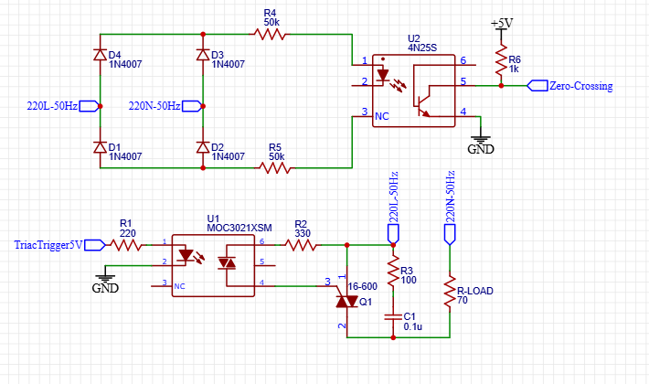
 I'm making a resistive load with control using Arduino and MOC3021 with BTA16-600 TRIAC. But I had a struggle. The output of controller is fine (I measured 5 V at output and 1.2 V in pin 1 & 2 of MOC3021 then I think it just fine, but when I measured the waveform through oscilloscope it just show a flat line rather than a wave created by the zero-detecting). However, the BTA16-600 didn't turn on. I measured the gate current is absolute 0.
Can you help me to figure out where was I wrong? Thank you very much.
If the image cant be show, here is backup link: https://ibb.co/XV6z4Kg
\$\begingroup\$
\$\endgroup\$
Add a comment
|
1 Answer
\$\begingroup\$
\$\endgroup\$
6
You have R5 connected to NC rather than the LED, so you won't get any zero crossing signal, and your controller won't have that input.
You can jumper pins 2 and 3 together.
Also, the MOC3021 and series resistor should go between MT2 and gate, which are pins 2 and 3 on the BTA16, not pins 1 and 3.
-
\$\begingroup\$ Sorry for wrong drawing, but i actually connected right in the reality it still didnt work \$\endgroup\$ Commented Jul 17 at 7:16
-
\$\begingroup\$ I don’t think it will work unless the zero crossing is working, but your triac connections are also wrong. \$\endgroup\$ Commented Jul 17 at 7:50
-
\$\begingroup\$ Can you figure out about triac connection sir \$\endgroup\$ Commented Jul 17 at 7:54
-
-
1\$\begingroup\$ Thank you very much, it worked \$\endgroup\$ Commented Jul 17 at 11:19
