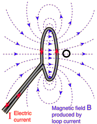
loop is made from a 10GHz microwave SMA cable, with one end cut off and tied in a loop, and is about a cm.
That's not a small loop antenna – a small loop antenna has a circumference that is relatively small, compared to the wavelength. Wavelength at 10 GHz is 30 mm, so the circumference \$l\$ needs to be \$l\ll 30\,\text{mm}\$, and 1cm is not \$\ll 30\,\text{mm}\$.
This is more of a medium-sized loop: not small enough for the loop not to matter to the far-field, not large enough for the feed to not matter to the far-field.
Also, just tying an end in a loop will not yield a good loop antenna - it will first and foremost leave you with a massive impedance mismath, and field mostly radiating from the cable's sleeve, not your loop.
This isn't some LF band loop antenna, where the cable, distance to the transmit amplifier and so on are inherently tiny compared to wavelength. You'll probably want to design a PCB that has a proper, impedance-matched connector for your coax cable, and impedance-controlled lines to a microwave distributed element Balun, which directly integrates into your loop, and also applies relatively massive impedance transformations.
So is there a simple approximate for B-field strength of a loop antenna when driven at 10 GHz?
Even when properly designed, this will depend on influences such as the feed line, which physically can't be so small that it's negligible to the size of the loop. So, no, there's no simple formula, you'll need to sit down and learn how to do an electromagnetic simulation of the whole system.
Also note that basically all "simple" formulas you find for antennas describe the far field, more than a wavelength away from the antenna. Now look at where your magnet sits: it's right in the reactive near field! Depending on just how small the magnet is, it will directly interact with the antenna, changing its properties.
So, there's really no way around a proper simulation, probably of a performance RF-material PCB with the loop, balun, impedance matching, and feed line printed on it, and probably also the magnet material in the right place.
Doing this all on a PCB also has the very distinct experimental advantage that things actually become repeatable – again, your wavelengths are in the millimeters, so small changes in mechanical bending will not allow you to produce the same antenna twice. Even a barely OK-quality board would improve that situation and save you a lot of time, and consequently money.

