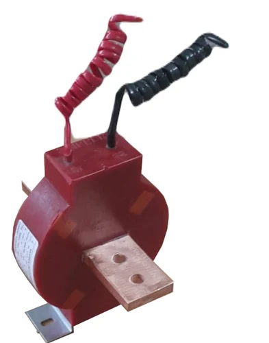
Calculations carried out in 1999 verified that the core does not go into saturation in the case of both DC and AC at 50Hz.
In the case of DC, we can use Ampere's Circuital Law, which tells us that the line integral of the magnetic field strength along some closed curve is equal to the total current passing through any surface enclosed by that closed curve.
If we choose our closed curve to be a circle within the body of the toroid, with a center on the axis of the toroid, then the field strength will be constant along the circle, and inversely proportional to the circumference of the circle. The field strength will thus be maximal in a circle that is on the inner diameter of the toroid.
(Typically, the closed curve that is chosen is a circle that passes through the center of the cross-section of the toroid. Since the values of the permeability of the core material and of the maximum flux density are not know precisely, such a choice of the closed curve gives adequately accurate results. However, I believe choosing a circle on the inner diameter of the toroid is a better choice, especially if the inner diameter and outer diameter are significantly divergent.)
Because we are considering the case where the line current is DC, there will be no transformer action, and no secondary current. Thus, the total current linked by our circle will just be the line current.
The ratio between the flux density in our circle, and the current passing through the donut hole of the toroid will be given by
$$\frac{B}{I_p} = \frac{45000 \times 4\pi \times 10^{-7} }{2\pi \times 45 \times 10^{-3}} = 0.2 \; \text{H}/\text{m}^2 = 0.2 \; \text{T}/\text{A}$$
Since your maximum flux density is said to be 0.8T, by my calculations, the maximum DC current that can pass through the CT without saturating the core is 4 A.
Of course there is a possibility that I made a mistake and you should verify for yourself.
In the case of 50 Hz AC, we do not need to consider the case where the secondary is short circuited. If the core does not saturate with 500 A line current and a 200 ohm burden, it will not saturate with a shorted secondary.
We will again use Ampere's Circuital Law (ACL), even though it is not exact for AC magnetic circuits. It will be close enough. The equation to use if you want an exact solution is Ampere's Circuital Law with Maxwell's Correction. However, that law adds complexity to the calculations, and since the values for other parameters are known only to an approximation, there is not a great deal of benefit to be had by using the more exact equation in this case.
In the AC case, there is both current flowing through the line, and current flowing in the opposite direction through each of the turns of the secondary. If the CT were "ideal", the secondary turns times the secondary current would be exactly equal to the primary (line) current. Thus the total current through the surface bounded by our circle would be 0, and there would be no flux in the toroid. So clearly, we must not assume that the transformer is ideal. Rather, we assume that the transformer consists of of two coupled inductors.
The formula for the inductance factor for a toroidal core with rectangular cross section is:
$$A_L = \frac{\mu h}{2\pi}\text{ln}\left(\frac{o.d.}{i.d.}\right)$$
Plugging the values of \$\mu = 45000 \times 4\pi \times 10^{-7}\$, \$h=0.035\$ and \$\text{ln}(o.d./i.d.) = 0.442\$ into the equation we get
\$A_L = 139.2 \;\mu\text{H}/\text{turn}^2\$
This is very close to the value of \$ A_L = 1.374 \times 10^{-4}\$ H per turns squared found in the original post using the formula for \$A_L\$ for solenoids.
Assuming ideal inductors, and a coupling factor of 1, the inductance of the primary would then be 139.2 \$\mu\$H, the inductance of the secondary would be 1.392 H, and the mutual inductance would be 13.92 mH.
For coupled inductors the phasor voltage of the secondary in terms of the phasor currents of the primary and secondary are:
$$v_s = j\omega Mi_p - j\omega L_Si_s$$
But
$$v_s = i_sR_B$$
where \$R_B\$ is the burden resistance.
this gives us
$$i_s = \frac{j\omega M}{R_B + j\omega L_s}i_p$$
The net current that magnetizes the core is
$$i_m = i_p - Ni_s$$
With a little algebra,
$$i_m = i_p\left(\frac{R_B}{R_B+j\omega L_s}\right)$$
and
$$\frac{|i_m|}{|i_p|} = \frac{R_B}{\sqrt{R_B^2 + \omega^2L_s^2}}$$
Plugging in \$R_B=200\$, and \$\omega L_s = 437.3\$ gives
$$\frac{|i_m|}{|i_p|} = 0.416$$
If I have not made a mistake, it seems that to keep the peak magnetization current less than or equal to 4 A, with a 200 \$\Omega\$ burden, the peak primary current (total) would need to be less than \$4 / 0.416 = 9.62\$ A, which is far below the 500 A specified in the original post.
This is not surprising. My guess is that either the specification for the burden resistor, or for the secondary current is incorrect. The power dissipated by the burden resistor is \$I^2R\$. For a current of 5 A, and a burden resistor of 200 \$\Omega\$, this would be \$25*200 = 5000\$ W. Although there are resistors of that size (for example brake resistors in machinery) it does suggest that one take a second look at the current and burden resistor specs.

