2
\$\begingroup\$

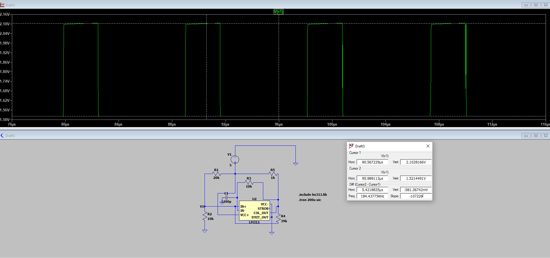
I need a little help solving some electronics problem. I need to calculate the charging and discharging time of a capacitor in the following Schmitt trigger astable circuit using LM311 I found. If I know that frequency is 100 kHz (stated on the datasheet).

enter image description here

The LTspice model of LM311 I found here.

I've calculated lower and upper threshold voltage on noninverting node using KVL and case for Vout=0 and Vout=5 and I've calculated Vtl=1.423 and Vth=2.15 which is somewhat similar to the simulation.

enter image description here

Using the charging formula for capacitor:

Vc(t)=Vinf+[Vinitial-Vinf]*e^(-t/R1 * C)

where Vinf is 5V and starting from the scenario where Vc(t)=Vth and Vinitial=Vtl I've calculated that time for which capacitor is charring is t1=2.726 microseconds, in the simulation it's 2.61 microseconds.

enter image description here

On calculating the discharging time, I used the same logic and formula for charging

Vc(t)=Vinf+[Vinitial-Vinf]*e^(-t/R1 * C)

Where Vc(t) is now Vth and Vinitial is Vtl and Vinf is 0 and calculated that time for discharging(t2) is 4.94 microseconds, or by using Vc(t)=Vthe^(-t2/R3C) I got that t2 is 4.94 microseconds, which is way off compared to simulation: enter image description here
If I calculate the frequency using the results of my calculation 1/4.94us + 2.61us I'm getting around 132 kHz which is way off 100 kHz stated by the datasheet. I'm obviously doing something wrong here. My question is:

  1. For these calculations can I assume that the capacitor is only charging and discharging only through R3 or do I need to somehow calculate equivalent resistance seen by the capacitor using Thevenin theorem, for example. If so, can I get assistance, I'm having a bit of trouble finding Vtev and Rtev? Or perhaps I can use superposition?
  2. Can I assume 5 V and 0 V for Vout like I did in calculating Vth and Vtl?

I know this may be trivial, but I'm stuck here and I would appreciate some help. Thanks in advance.

\$\endgroup\$
0

2 Answers 2

1
\$\begingroup\$

First, we need to find the threshold voltage. If we assume that LM311 is LOW (0V) then the voltage at V+ will be equal to:

$$ V_{TL} = V_{CC} * \frac{R_2||R_4}{R_1 + R_2||R_4} = 5V * \frac{7.96k\Omega}{27.96k\Omega} = 1.42V$$

And the second threshold will be when LM311 output is HIGH (pull high by R5 resistor). And this time the voltage at V+ input will be:

$$V_{TH} = V_{CC} * \frac{R_2}{(R_4+ R_5)||R_1 + R_2} = 5V*\frac{10k\Omega}{23.34k\Omega} = 2.14V$$

Now we can calculate discharge and charge time. This discharge time can be found using this equation:

$$T_D = RC* \ln \left( \frac{V_{TH}}{V_{TL}}\right) = 5\mu s$$

And the charging time:

$$T_C = RC* \ln \left( \frac{V_{CC} - V_{TH}}{V_{CC} - V_{TL}}\right) = 1.2nF*(10k\Omega + 1k\Omega)\ln \left( \frac{5V - 2.14V}{5V - 1.42V}\right) \approx 2.964 \mu s $$ This is not strictly true because Vinf will not be exactly equal to 5V. But since R5 is much smaller than R4 we can ignore this. Also, I ignored the R3 loading effect when calculating the threshold voltage
This means that the frequency should be around \$125kHz\$. In LTspice I measured \$128.5kHz\$

How to find those RC time formulas can be found here:

A capacitor and a neon lamp focused circuit problem

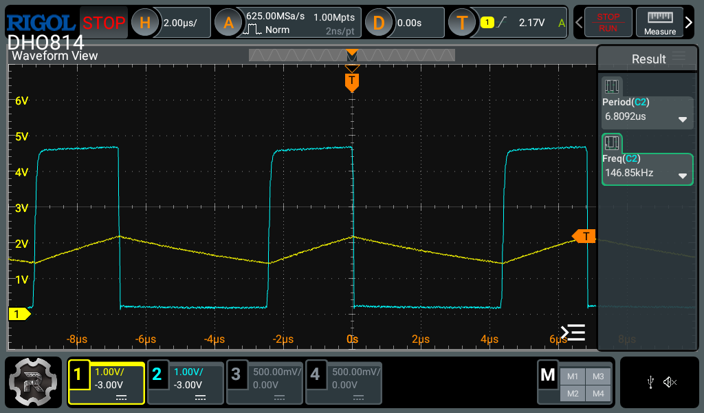
I also breadboard the circuit but instead of a 1.2nF capacitor, I used a 1nF capacitor. Thus, we have: \$T_D = 4.1 \mu s \$ and \$T_C = 2.527 \mu s \$ Therefor \$F = 150kHz\$

And this is what my scope shows: enter image description here

enter image description here

As we can see the measured frequency is around \$147KHz\$ not bad.

\$\endgroup\$
2
  • \$\begingroup\$ Thank you for your response and answer. My question now is would the time constant be the same if we lower R4 to something like 10k i.e. (R3+R5)*C or would I need to take into account R4 i.e. (R3+R5llR4)*C ? \$\endgroup\$
    – Andrija
    Commented Jul 25 at 11:41
  • 1
    \$\begingroup\$ If you lowered the R4 resistor you should notice that it will have a bigger influence on both threshold voltage than on the time constant. ( R3 + R5||( R4 + R1||R2) )*C \$\endgroup\$
    – G36
    Commented Jul 25 at 17:36
1
\$\begingroup\$

I calculate the threshold voltages at 1.45V and 2.14V using an output voltage of 0.17V (low) and 5V (high), taking into account the 1K pullup (but not the 10k to the capacitor).

Simulated values are 1.44V and 2.10V. The simulated low output voltage is 0.13V.

The discharge time between the calculated thresholds is

Vc(t) = \$0.17 + 1.97e^{-t/RC}\$ which, for an end voltage of 1.45V gives us a time of 5.17us. Simulated is 4.93us, within about 5%.

Simulated frequency is 128.5kHz using model LM311/TI.

We are ignoring a bunch of things such as input and stray capacitance, loading effect of the 10k to the capacitor, and any TTL DTL loads connected to the output, comparator propagation delay (which depends on the rate of change of input voltage) etc.

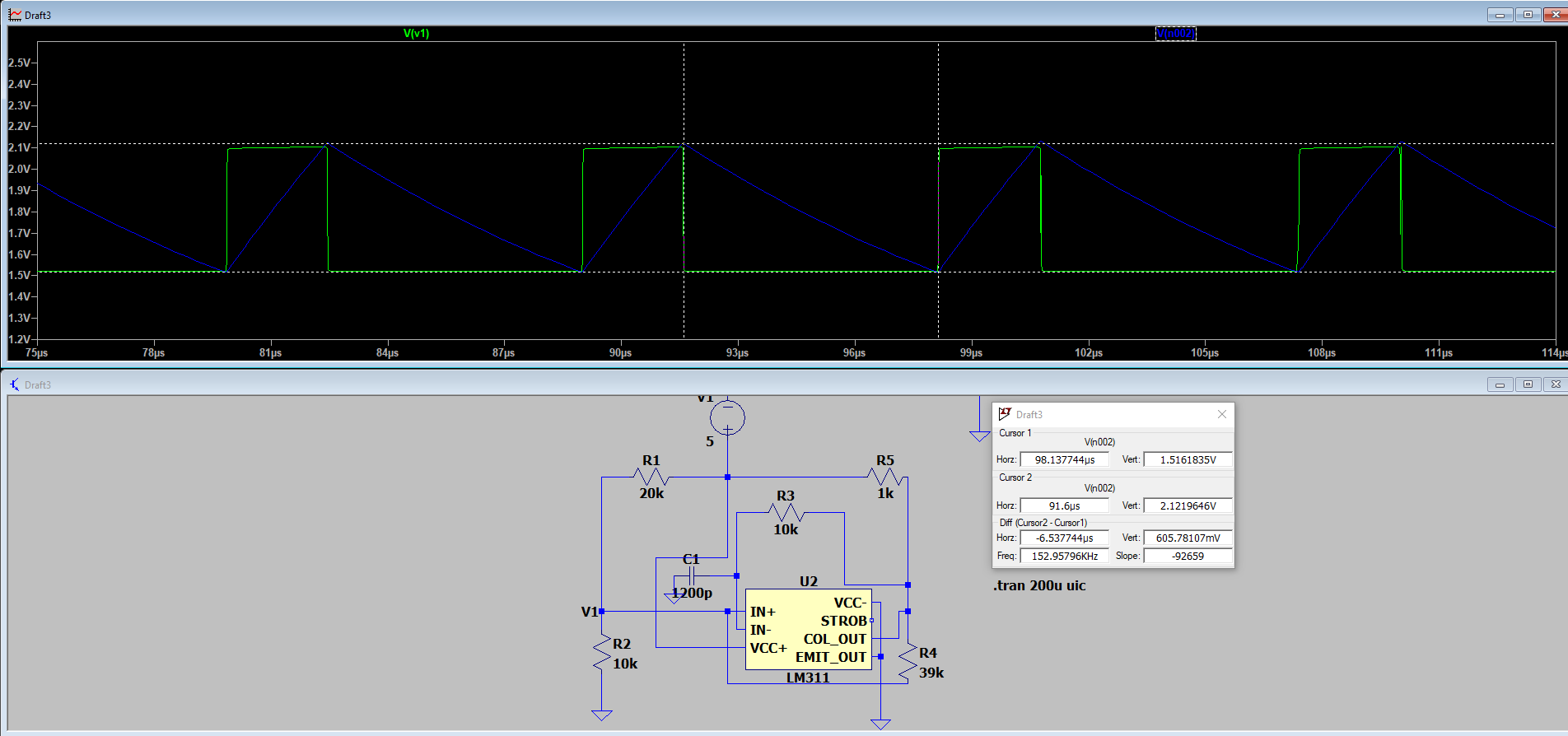
If you look at the output voltage you'll see it (simulated) goes from 0.13V to 4.7V or so, so using 0/5V should get you within the ballpark provided the thresholds are well away from those voltages. I corrected for some of the 4.7V by assuming a 40kΩ resistor (39k + 1k).

I would expect that if you actually built this circuit on a PCB you'd get around 120~130kHz, and a bit lower if you built it on a solderless breadboard.

You should not believe everything you read in datasheets, particularly the suggested circuits at the back of linear IC datasheets (not to be confused with the 'typical application' diagrams, which are usually spot-on), some of them are total caca for real applications. This one appears to be 'close but no cigar'.

Note the (small-ish) effect of the capacitor charging on the 'high' output voltage:

enter image description here

\$\endgroup\$

Your Answer

By clicking “Post Your Answer”, you agree to our terms of service and acknowledge you have read our privacy policy.

Not the answer you're looking for? Browse other questions tagged or ask your own question.