I am using micro electrodes in a conductive solution (PBS: Phosphate Buffered Saline) and I would like to be able to measure the voltage with a National Instrument measuring device (PXIe6345).
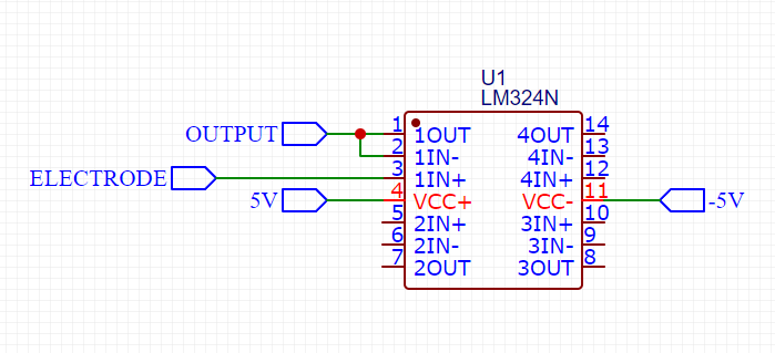
I apply a voltage in the bath (a sinusoid 10 Hz and 50 mV amplitude). I have a very high impedance due to the conductive solution and the small size of the electrode (about 10-20M ohm). My measurement system switches very quickly between several inputs, so I need a low impedance so that the internal capacitor has time to reach the right voltage. To do this, I want to make a voltage follower with an LM324N and a +/-5 V voltage source (RT-50A Mean Well USA).
The circuit is very simple, but I have a result that I don't understand, and I hope that people here can help me.
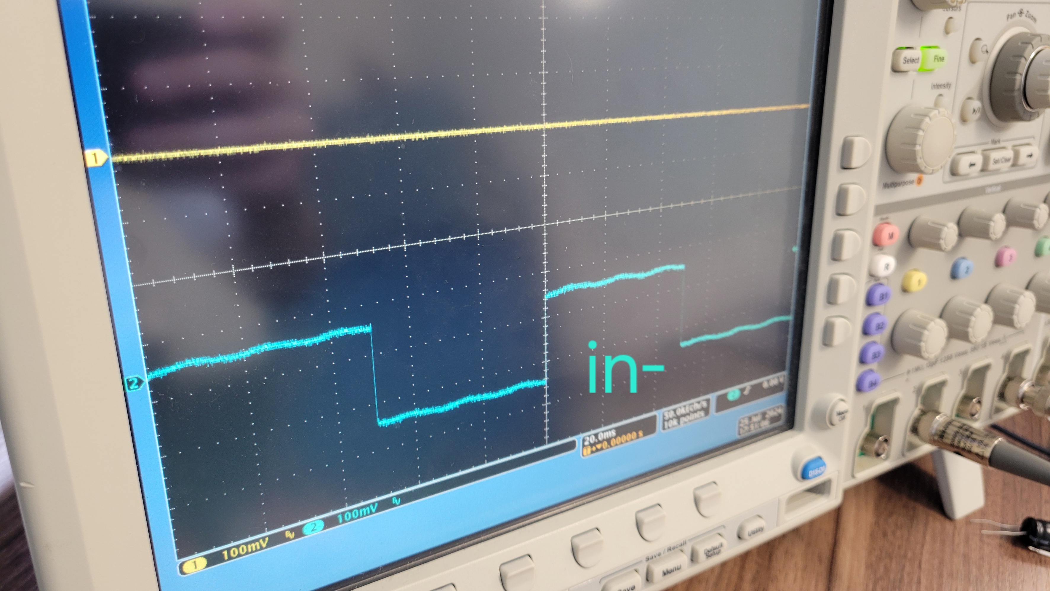
I have a voltage offset because my generated signal is centered on zero volts, plus I have a drift effect towards the positive which seems to be abruptly compensated after a certain value, see the picture.
Edit 1:
Following the advice I received here, I bought an LMC660, but I'm still having the same problems.
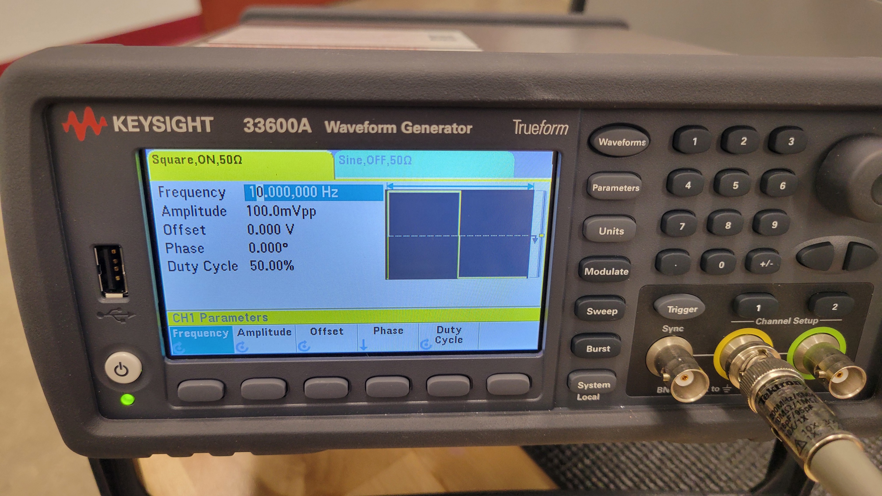
I did some measurements with an oscilloscope to try to find the problem. This time in my setup I added resistors to put a gain of 5 to the output signal (16K ohm and 4K ohm resistance). I also added a 100 ohm resistor on the output. Here are some photos I took of the circuit and the oscilloscope (sorry for the reflections from the sun).
The signal seems to be correct apart from the offset still present on the op amp output signal.
I think the IN+ signal looks like this because of my oscilloscope's ability to read high impedance values rather than this being the true IN+ signal because the op amp output is correct.
(If it's not a question of current bias as suggested, could it be due to breadboard ?)
Edit 2:
I've just tried to see if there could be a galvanic battery effect, but I haven't measured any voltage between two electrodes once they've been disconnected from everything.
Edit 3:
Finally, there seems to be 10mV between certain electrodes on the electrode matrix that I use when the system is not connected to anything. However, even with a gain of 5 this alone cannot explain the almost 1V offset in the previous photos.
Edit 4:
I've also just realised something: when I want to measure the voltage between the reference electrode and the electrode I'm measuring with a voltmeter in parallel, the offset gradually decreases until it almost cancels out - see the images below.
I imagine this is due to the high impedance of my signal after passing through the bath, which means that the current passing through the voltmeter is able to influence it.
Thanks again to those who will take the time to reply.


