0
\$\begingroup\$

I have a negation operation and two types of "logic gates" with following outputs (A, B are inputs):

"gate" 1:

A | B | OUT
x   0    1
0   x    1
0   0    1
0   1    x (no output)
1   0    x (no output)
x   x    x (no output)
1   1    0
x   1    0
1   x    0

"gate" 2:

A | B | OUT
x   0    0
0   x    1
0   0    x (no output)
0   1    1
1   0    0
1   1    x (no output)
x   1    1
1   x    0
x   x    x (no output)

I can join these two "gates" to form the third one:

A | B | OUT
x   0    x (no output)
0   x    1
0   0    1
0   1    1
1   0    0
1   1    0
x   1    x (no output)
1   x    0
x   x    x (no output)

Is it possible to use these (half gates or joined gates) to build regular binary logic NOR or NAND gates, given that it is possible to additionally negate any input and/or output?.

Negation op is:

A | OUT
x    x (no output)
0    1
1    0

The problem

The main difficulty is to make the "joined gate" inputs (0,1) and (1,0):

A | B | OUT
0   1    1
1   0    0

to always output 1 or 0 like:

A | B | OUT
0   1    0
1   0    0

This is the only change needed to get the NOR gate. The question is how to do it with these "gates", if it's possible at all.

\$\endgroup\$
12
  • 1
    \$\begingroup\$ Your "joined gate" is NOT(A) (the B input is irrelevant to the output) so not helpful at all given that you stated already have negation for free. By no output do you mean don't care or do you intend something like high impedance (like in a multiplexor arm?) \$\endgroup\$ Commented Jun 9, 2013 at 18:47
  • \$\begingroup\$ The question is impossible to answer in its present form because you've introduced gates that have three output states, but have not defined their behavior for all three states on their inputs (other than to say that NOT(x) = x). \$\endgroup\$
    – Dave Tweed
    Commented Jun 9, 2013 at 18:55
  • \$\begingroup\$ @DaveTweed: just fixed that \$\endgroup\$
    – PSz
    Commented Jun 9, 2013 at 19:08
  • \$\begingroup\$ If the question is if these are equivalent to "regular binary logic NOR or NAND gates", which also don't specify behavior for "x" inputs, then how is the behavior of these gates when they have "x" inputs relevant at all? \$\endgroup\$
    – Phil Frost
    Commented Jun 9, 2013 at 19:12
  • 2
    \$\begingroup\$ @PiotrSzturmaj How you represent x electrically is irrelevant. What does a NAND or NOR gate do when an input is x? There is no answer, because the behavior of a NAND or NOR gate is only defined if the inputs are true or false. So, what your gates do when any input is x is also irrelevant: we can say the behavior is undefined, just like a NAND or NOR gate. \$\endgroup\$
    – Phil Frost
    Commented Jun 9, 2013 at 19:24

3 Answers 3

1
\$\begingroup\$

I'm trying to build the NOR/NAND gate with the use of inductively coupled coils. This is my personal interest and research :) I'm trying to prove (or disprove) that it's possible to build asynchronous logic circuits in this way.

Why didn't you ask that in the first place? It would have saved a lot of time.

Yes, it is possible to build logic with transformers. Have you ever heard of "rope memory"? It's a form of read-only memory built entirely from wires and ferrite toroids. It was used, for example, to store the instructions in the Apollo guidance computers.

The point is, a ROM (any ROM, no matter what the technology) is essentially a huge matrix of AND and OR gates, so it meets your basic functional requirement. However, it depends on exactly what you mean by "asynchronous" in this context. Transformers do not couple energy from DC signals, and so magnetic logic of this type is always driven by pulses, not DC currents.

\$\endgroup\$
4
  • \$\begingroup\$ Thank you for the answer, however I'm not trying to build ROM but simple AND/OR/XOR gates (which can be build from NOR or NAND). For asynchronous circuit, see en.wikipedia.org/wiki/Asynchronous_circuit - it basically means circuit without a clock. Yes, I know it must be driven by pulses. \$\endgroup\$
    – PSz
    Commented Jun 9, 2013 at 20:08
  • 1
    \$\begingroup\$ You can make a ROM as small as you like. A ROM with two inputs and one output is called a "gate". \$\endgroup\$
    – Dave Tweed
    Commented Jun 9, 2013 at 20:12
  • \$\begingroup\$ This is interesting, could you clarify it a bit? Is it possible to build an adder with those "gates"? \$\endgroup\$
    – PSz
    Commented Jun 9, 2013 at 20:20
  • 1
    \$\begingroup\$ I'm hardly an expert. But I think if you understand in detail how the address decoding in rope memory works, you'll gain a lot of insight into the concepts behind magnetic logic in general. You have to dig for it, but the information is out there. \$\endgroup\$
    – Dave Tweed
    Commented Jun 9, 2013 at 20:50
1
\$\begingroup\$

If I'm understanding this question correctly, you're dealing with trinary logic, where you have three states 0, 1, and x. You have two trinary gates: g1 and g2. (Note that the truth table for g2 is in a different order than g1) You want to create NAND and NOR gates out of these gates. I assume that you only care about 0 and 1 inputs to the NAND and NOR gates and don't care what they output for an x input.

I made a Python program to brute-force try gate combinations and found ways to generate NAND and NOR. For NAND, use g1(g1(1, g1), g1(g1, g1)). For NOR, use g2(g1(g1, g1), g2(1, g1)). [The "leaf" gates take A and B as inputs.]

To understand the NAND logic, note that g1 in effect is a "NOT majority" gate. It checks if there are more 0 or 1 inputs and outputs 1 for majority 0, 0 for majority 1, and x for tie.

So g1(g1, g1) applies "NOT majority", doubles, and applies "NOT majority" again, which is just the "majority" function. Meanwhile, g1(1, g1) does "NOT majority", provides another 1, and does "NOT majority" again, yielding x if there is a majority of 1 inputs and 0 otherwise. Finally, applying g1 to these two sub-results yields 0 if there is a majority of 1 inputs and 1 otherwise, which is the desired NAND logic.

\$\endgroup\$
0
\$\begingroup\$

HUL logic

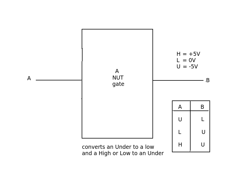
I think your basic idea is faulted because in your system the OUTPUT of one gate cannot connect as (a defined) INPUT to another. A 'floating' input cannot be determined. Binary logic works because there are TWO defined (and related) states. Your system has THREE states (Trinary logic). but doesn't define the third state in terms of the other two. Instead of using a state that cannot be tested for (no output) why not give it a value that is different to '1' (high) and '0' (low) but related to them. I would suggest something like

HIGH (a positive voltage/current), LOW (about zero voltage/current) and UNDER (a negative voltage/current)

It would then be relatively easy to detect each (voltage or current) state (H,U,L) and construct a 'gate' according to some logic with the inputs or outputs either positive, 0 or negative.

enter image description here

\$\endgroup\$

Your Answer

By clicking “Post Your Answer”, you agree to our terms of service and acknowledge you have read our privacy policy.

Not the answer you're looking for? Browse other questions tagged or ask your own question.