0
\$\begingroup\$

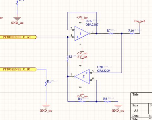
I measure temperature with the PT100 temperature sensor. With the circuit below, I obtain a constant DC current of 1.5 mA. I use tempref value as 3 volts and R2 resistor value as 2k.
Although this current circuit works, does anyone have a suggestion for a different current source circuit that will produce 1.5mA constant DC current in order to see a different circuit design?

Or what steps or changes can I follow that can be improved or increased efficiency in the circuit I made? Current Source Circuit

\$\endgroup\$
0

2 Answers 2

1
\$\begingroup\$

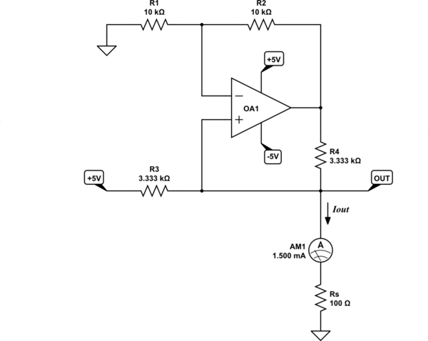
A howland current source does not require a second buffer op-amp if the desired output current is only 1.5mA, and with careful selection of resistors, the positive +5V supply can be used as the reference voltage. Resistor Rs is your PT100:
schematic

simulate this circuit – Schematic created using CircuitLab

This requires \$R_3 = R_4\$, so that:

$$ I_{OUT} = \frac{5V}{R_3} $$

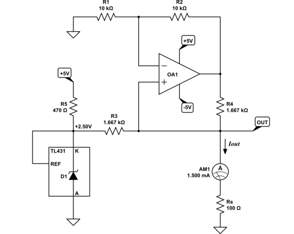
This has the problem that any noise present on the +5V supply rail will be injected into the signal, and some fraction of it will appear at the output. If you have a precise and clean +5V supply, then that's not a problem, but a noisy supply (like a DC-DC converter output) would require that you produce some precise ground-referenced and low-impedance source. Here I use the TL431 to produce exactly +2.5, and adjust R3 and R4 to suit:
schematic

simulate this circuit

The above solutions require the op-amp to be powered from both positive and negative supplies, since the OPA2209 op-amp cannot operate with inputs close to the negative supply. See the bottom of page 6 of the the OPA2209 datasheet, a parameter called "Common-mode voltage range". The op-amp inputs in the above design hover at +150mV, very close to ground potential, meaning you can't use ground as the op-amp's negative supply.

If this is the only part of your system using the −5V supply, then you can simplify the design by using an op-amp with a wider acceptable input voltage range, such as the LM358, which will work well with input voltages right down to its own negative supply potential. That can then be 0V (ground), instead of −5V.

Doing that, the op-amp won't be able to output 0V. An LM358 will certainly get its output below +100mV, corresponding to sense resistance \$R_S\approx 30\Omega\$, at a temperature of about −170°C.


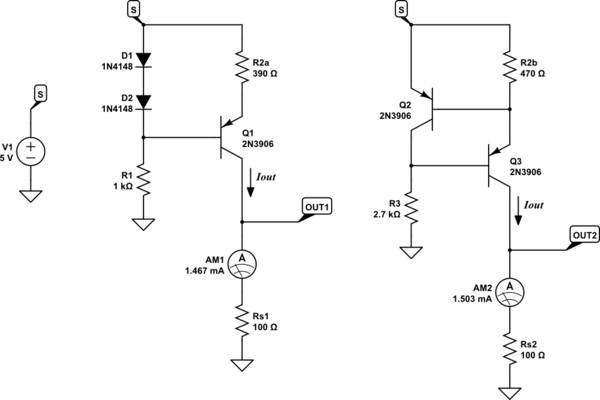
If precision isn't so important, consider these transistor-based designs:
schematic

simulate this circuit

Adjust R2 to set current:

$$ I_{OUT} \approx \frac{0.7V}{R_2} $$

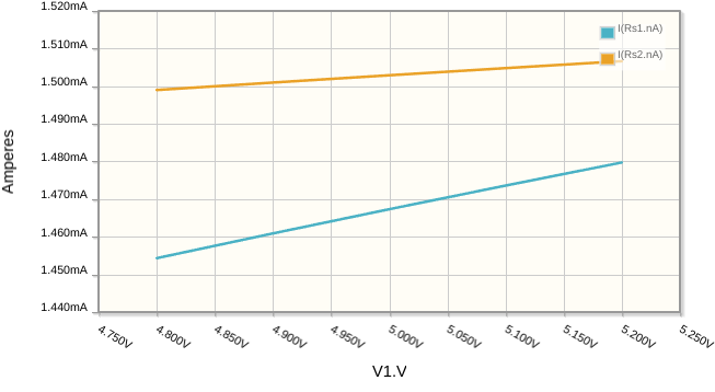
This is variation in \$I_{OUT}\$ as supply voltage varies from +4.8V to +5.2V:
enter image description here

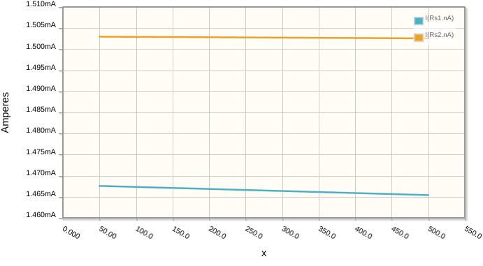
This is how \$I_{OUT}\$ changes as PT100 resistance \$R_S\$ varies from 50Ω to 500Ω:
enter image description here

\$\endgroup\$
1
\$\begingroup\$

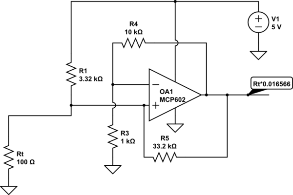
Here's one way:

schematic

simulate this circuit – Schematic created using CircuitLab

This circuit will work with Rt as high as about 270Ω, corresponding to more than 450°C for a DIN \$\alpha = 0.0385\$ sensor (the most popular type worldwide).

Most of the current is supplied by R1 even at maximum output (between 0 and about 120uA comes from the op-amp output). You can increase R4 and R3, keeping the ratio, to further reduce the loading.

Because R1 is dominant (a side-effect of the maximum voltage across the RTD being low wrt the supply voltage) the usual drawback of a Howland-style source (sensitivity to resistor mismatch) is not as significant.

The output is from 1.657V to 4.4728 for 100 to 270Ω input. You can go directly (or through a passive LPF) into an ADC that uses the same 5V reference and the supply voltage magnitude cancels out.

Note I've picked standard E96 resistor values that result in slightly more than 1.5mA nominally. To get a constant current, for R4/R3 = 10, R5 should be 10x R1 and the nominal current Io is just 5V/R1. Op-amp output voltage is \$V_{out}=I_0 Rt (1+R4/R3)\$.


You can also simply use a series resistor to the voltage reference and correct for the slight nonlinearity in firmware. A simple resistor gives you a current that is constant within a few % for changes from 100Ω to 200Ω. The RTD is slightly nonlinear anyway, which you probably want to correct for anyway, so it's just different coefficients. This works well if you are using an ADC with a PGA.

\$\endgroup\$

Your Answer

By clicking “Post Your Answer”, you agree to our terms of service and acknowledge you have read our privacy policy.

Not the answer you're looking for? Browse other questions tagged or ask your own question.