0
\$\begingroup\$

I'm new to learning about how to use Karnaugh maps to optimise truth tables into efficient logic circuits, and have been following Dave Jones' excellent tutorial.

As an example to work on, I have chosen to try to make a quadrature decoder logic circuit, such as one might use to read the signals from a rotary encoder.

My rotary encoder is a simple non-absolute position type meaning that it has two square wave outputs (lets call them A and B), 90 degrees out of phase.

By definition this means that A and B can never change state simultaneously, as their phase relationship is etched into a glass disk!

However, these states do need to be included in the Karnaugh map in order for it to be a valid one.

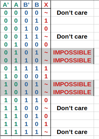
So the normal truth table is shown below. A' and B' are the previous values of signals A and B respectively, sampled at the previous clock cycle X is the output logic level which indicates a clockwise move (0) or a counter-clockwise movement (1)...

enter image description here

So I have two interesting conditions to deal with. The lines marked "Don't care" are simply cases when the encoder has not moved at all, so the output X doesn't matter. Then there are the impossible conditions mentioned above.

Note: I will need a second output Y that will act as a "move detected" pulse.

Question:

What do we do with "don't care" or "impossible" output conditions when constructing our Karnaugh map?

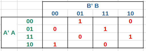
I believe this is what the KM should look like for the above truth table, but I have omitted the cells that I am unsure about...

enter image description here

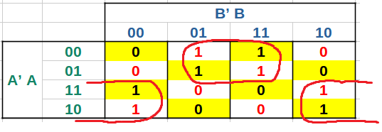
My naïve brain wants to think that it would be convenient to just arbitrarily write 1 in some of these empty cells to make grouping of the real 1s easier.

If I do so then I can group the ones like this for a simple solution of only 2 bit groups...

enter image description here

So my final logic expression would be ((not A') and B) or (A' and (not B)).

But is this a valid way to solve this problem? I like the idea but it feels wrong somehow. Will this break the logic for the outputs that we DO care about?

\$\endgroup\$
11
  • \$\begingroup\$ there's exactly one way we would use to figure that out: put in all possible input combinations, and see whether what we get is what you specified should happen. And, I think you'd do the same! \$\endgroup\$ Commented Aug 24 at 14:13
  • \$\begingroup\$ @MarcusMüller, if I understand you correctly then I was wrong about my extra Y signal being irrelevant. The Y signal is what prevents the "imaginary" 1s from causing problems elsewhere. Because there will be no Y pulse when an imaginary 1 bit is active. Makes sense I think. \$\endgroup\$
    – Wossname
    Commented Aug 24 at 14:25
  • \$\begingroup\$ @MarcusMüller, And yes I get what you mean by basically "brute forcing" each possible input, but I'm interested in the general approach. Is it scalable to hundreds of inputs, which would be hard to brute force? Just curious. \$\endgroup\$
    – Wossname
    Commented Aug 24 at 14:30
  • 2
    \$\begingroup\$ As an aside, a single rising edge D-Flip Flop will give you X. You connect A to the data input, and B to the clock input. The Q output will then give you the direction. The advantage is that its tolerant to noise and denouncing. \$\endgroup\$ Commented Aug 24 at 14:52
  • 1
    \$\begingroup\$ @Wossname in general, yes. In many cases, the question "is there a five-operations or fewer expression giving me the desired output" is a "boolean satisfiability problem", and that is a class of NP-complete problems; modern SAT solvers have heuristics that find a possible solution in much shorter time. I don't know which problem you'd really solve with an Karnaugh map if you have hundreds of inputs. (say you have a hundred boolean inputs – your karnaugh map becomes 2¹⁰⁰ entries large. I don't think that is a scalable approach: verification solutions takes less time than coming up with them) \$\endgroup\$ Commented Aug 24 at 15:11

2 Answers 2

3
\$\begingroup\$

Generally speaking how you consider "impossible" input states in a Karnaugh Map is entirely up to you and your requirements.

In some cases it makes sense to treat them as 1's or 0's depending on what it would mean if you did happen to detect that state.

In other cases, you could decide that it really doesn't matter what the output is for those input combinations, at which you treat it as being no different from "don't-care" values.

For "don't-care" values, you are free when choosing the groupings to select whether the output is a 1 or a 0. When drawing your groups, if you find that you can make a large box containing only 1's and x's, then you make the x's into 1's to complete the group and reduce the resulting logic size. If you find any x's left over not belonging to a group, you make them 0 so that they don't consume any logic.


As an aside, for a simple Quadrature Encoder, you can detect the direction of rotation using nothing more than a edge-sensitive D-Flip-Flop.

Connecting the A signal to the data input, and B to the clock input will give you a logic 1 at the DFF output for one direction, and a logic 0 for the other direction. Whether a 1 means CW or CCW rotation depends on the polarity of A and B, and whether the DFF is rising or falling edge sensitive. If you find that for your setup the output is inverted, you simply swap the A and B signals over which will invert the output.

Using a DFF like this makes for a design that is generally tolerant to noise and ringing on the edges - there is only one signal changing at a time, and it doesn't matter if there are multiple bouncing transitions, you will still get a stable output.

\$\endgroup\$
1
  • \$\begingroup\$ I just wanted to add that the problem of "I know only some input combinations are valid, I want to figure out the underlying info that lead to what I observed" (in this case, even input combination sequences) is very much a channel coding problem. \$\endgroup\$ Commented Aug 24 at 15:19
2
\$\begingroup\$

If a certain set of inputs to your logic are strictly impossible, then you don't care what output they produce.

For purely combinatorial logic like a decoder, I'd take this principle literally (assuming there is no way for the outputs to violate the user's physical safety).

If instead of a pure combinatorial logic you were designing a state machine, you'd probably want to be a bit more careful to make sure that the outputs don't cause the machine to get stuck if it enters an "impossible" state (for example due to an ESD event or power brown-out).

\$\endgroup\$
1
  • \$\begingroup\$ Under normal conditions, yes my inputs are strictly known. Physical damage would need to occur to allow the "impossible" states to be seen by the electronics. And at that stage, all bets are off! \$\endgroup\$
    – Wossname
    Commented Aug 24 at 17:16

Your Answer

By clicking “Post Your Answer”, you agree to our terms of service and acknowledge you have read our privacy policy.

Not the answer you're looking for? Browse other questions tagged or ask your own question.