3
\$\begingroup\$

It is said that the output impedance of an EMI filter needs to be largely lower than the input impedance of a converter in order to have no stability issues.

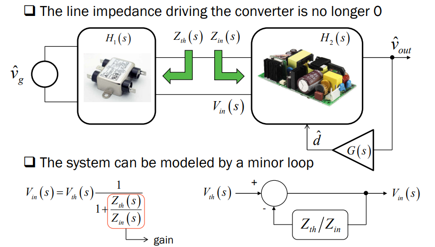
From this document written by Christophe Basso, there is this slide:

enter image description here

What I understand is that Zth is equal to the output impedance of the filter and Zin is equal to the input impedance of the converter.

As Zin correspond to the input impedance of the filter, by nature of a converter, the input impedance has a phase equal to -180°. It means that the input impedance is negative. So when the magnitude of \$Z_{in}\$ and \$Z_{th}\$ is equal, then the above transfer function goes to infinity, and it means that the transfer function is unstable and so \$V_{in}\$ is oscillating. (At this point from my side it does not mean that the output voltage of the converter is unstable? The input voltage could be oscillating without making the output voltage oscillating. There is something that I do not understand.)

Suppose I have a converter with a magnitude input impedance equal to 1 Ω at low frequencies. At low frequency, the output voltage is almost perfectly regulated and the phase of the input impedance is equal to -180°. Then I place an LC filter with a frequency resonance at high frequency. So the output impedance of the LC filter is almost 0 at low frequencies. (Particularly if I use a low inductor).

Then suppose I have a battery with an output impedance equal to 1 Ω at low frequencies. So it makes the transfer function goes to infinity. The magnitude of \$Z_{th}\$ and \$Z_{in}\$ are equal and the phase of \$Z_{in}\$ is negative.

I tried to simulate it under SIMPLIS, but I was not able to get results really convincing me.

Also, as it is necessary to have a certain margin between the output impedance and the input impedance, I wanted to see what would be the consequences of reducing the margin between the output impedance of the battery and the input impedance of the converter, but I was not able to see anything.

So my question is: Does the output impedance of a battery can have an effect on the stability of a converter if the input impedance of the converter is in the vicinity of the output impedance of the battery? I mean on SIMPLIS I am able to see the effect of an LC filter if it not correctly attenuated, and I see the effect on the stability margin. But an LC filter is largely different than just a DC resistor as output impedance like it could be on a battery. In the case of a resistor there is no modification of the phase contrary to an LC filter.

\$\endgroup\$
1
  • \$\begingroup\$ " by nature of a converter, the input impedance has a phase equal to -180°. " No, it doesn't, or at least it;s not guaranteed. \$\endgroup\$ Commented Aug 29 at 13:57

1 Answer 1

4
\$\begingroup\$

Well, we can simulate it pretty easily by inputting the functions.

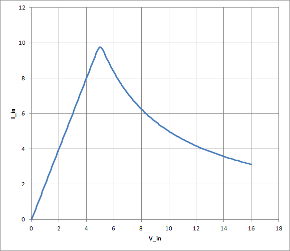
First, the input current. I'm using a regulated buck curve for stability reasons. That is, a curve like so:

input current curve

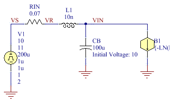
Consider a circuit like so:

schematic

I've cut off the full B expression but it appears below (mind a leading + is line continuation in SPICE). For stimulus, the source is stepping from 10 to 11V. The netlist is:

.PARAM Vo=5
.PARAM RL=0.5
.PARAM pow=3

B1 VIN 0
+ I={-LN( EXP(-V(VIN)*pow/RL) +
+ EXP(-LIMIT(Vo^2*pow/(RL*V(VIN)), -1e6, 80)) ) / pow}
CB VIN 0 100u IC=10
L1 VR VIN 10n IC=5
RIN VS VR 0.07
V1 VS 0 DC 0 PULSE(10 11 200u 1u 1u 1 2) AC 1 0

Waveforms:

VIN and V1[i]

Note that \$\sqrt{\frac{L}{C}} \ll R\$ so the circuit is resistance dominant, and we have an RC response. The RC time constant is about 7.2µs, or RIN * CB.

The operating point is ~10V 5A, and I = P/V in this range (>5V), so the incremental resistance is \$\frac{dV}{dI} = \frac{-V^2}{P}\$ or -2Ω. Increasing RIN to 1.5Ω, and raising source voltage to compensate for the drop (17.5V initial +1V step), gets:

VIN and V1[i]

Notice the ensuing step change at VIN is 2.5V, from an input of 1V -- we have voltage gain. The time constant is also much longer, about 333µs, implying Req = 3.3Ω. Since 1.5 is in circuit, the converter must have \$\frac{(1.5)(3.3)}{(1.5) - (3.3)}\$ = -2.75Ω, close enough. (It's not a simple RC curve, rather the nonlinearity is making itself evident; the final input resistance is -3.125Ω, so the 63% point measures a sort of averaged time constant and thus resistance inbetween the initial and final figures.)

If instead we set RIN to 0.1Ω and raise L1, we get oscillation. At first, it's damped; for 0.5µH, some overshoot is evident, but it's still well behaved.

Note that the resistance at VIN, at resonance, is not defined by a single circuit parameter here, but we have to calculate the equivalent. V1 is a dynamical short circuit, so we have an equivalent (RIN + L1) || CB network here, and we observe L1+CB are an L-match network, converting RIN from ESR at the source, to EPR at the load. For 0.5µH and 100µF, we have Zo = 0.07Ω, so comparable values of RIN give good damping. As we raise L1, Zo goes up as sqrt(L1), but EPR goes up as the square of Zo/RIN, thus proportional to L1. Since we're currently around 0.1Ω here, but the system should go unstable at 2Ω, it should remain stable for L up to about 20µH, but oscillate continuously beyond there.

Indeed, about 18µH sees it oscillating steady under initial conditions; but after the step, input negative resistance rises and damping increases (the poles move from ~on the imaginary axis, to just left):

VIN, V1[i] verge of oscillation

Notice the long time constant: the time axis is up to some ms now.

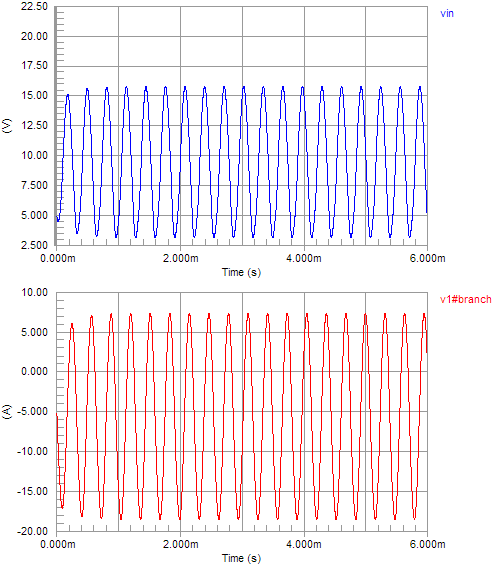
Forcing it into steady oscillation (CB IC=5, L1 = 24u), we see it does find a limit:

steady oscillation

but notice VIN is dipping below the dropout voltage, i.e. the output will have a cuspy-dips waveform, where regulation is achieved during the VIN peaks but voltage can only follow the input otherwise, and thus the load resistance acts in parallel with the LC for part of the cycle, dampening it -- thus the nonlinear curve that I constructed, acts to push the poles from the RHP (growing amplitude) back on axis (steady amplitude), when considering the effect averaged over a cycle.

(Note that pole-zero analysis only applies to purely LTI lumped-equivalent systems. We have to linearize a nonlinear or time-variant system in some meaningful way to apply the analysis. In this case, making a hand-wave about cycle-averaged effect, and ignoring harmonics perhaps, gives us some excuse to continue interpreting the system under this analysis.)

I could further model the converter as a dependent transfer system, or even model the regulator (controller), which will incorporate some dynamics of the loop (and thus affect AC input impedance, besides representing just the input bypass CB), but this is already getting quite long, and perhaps such can be left as an exercise for the reader.

\$\endgroup\$
3
  • \$\begingroup\$ Thank you for your answer, if there is no LC filter in your simulation, Just a résistor as an output impedance does it make the circuit oscillating ? If the resistance is higher than the input impedance of the converter ? \$\endgroup\$
    – Jess
    Commented Aug 29 at 18:43
  • \$\begingroup\$ My post was not clear but tthis is what I wanted to know. The exemple of the LC filter is always used but the rule talk about impedance and impedance is not limited to RLC, it could be simply a résistor \$\endgroup\$
    – Jess
    Commented Aug 29 at 18:57
  • \$\begingroup\$ In the small-L condition, the poles collapse to the real axis as well. That is, the oscillation period is infinite, which is to say the system is bistable. In practice, such a scenario usually stays in the un-started state (stuck on resistive slope, Vout < Vreg). See "load line" analysis for further reading. \$\endgroup\$ Commented Aug 29 at 19:55

Your Answer

By clicking “Post Your Answer”, you agree to our terms of service and acknowledge you have read our privacy policy.

Not the answer you're looking for? Browse other questions tagged or ask your own question.