1
\$\begingroup\$

I'm designing a power supply for an audio system, and I've heard that safety polypropylene capacitors are recommended for filtering high-frequency noise from switching components. I have one of these capacitors, but I'm concerned about connecting it incorrectly and damaging the entire power supply. How should I properly connect this capacitor to ensure both effective noise filtering and protection of my circuit?

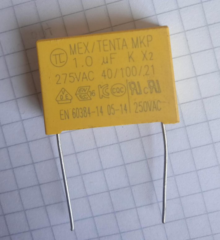
This is the capacitor I'm referring to. enter image description here

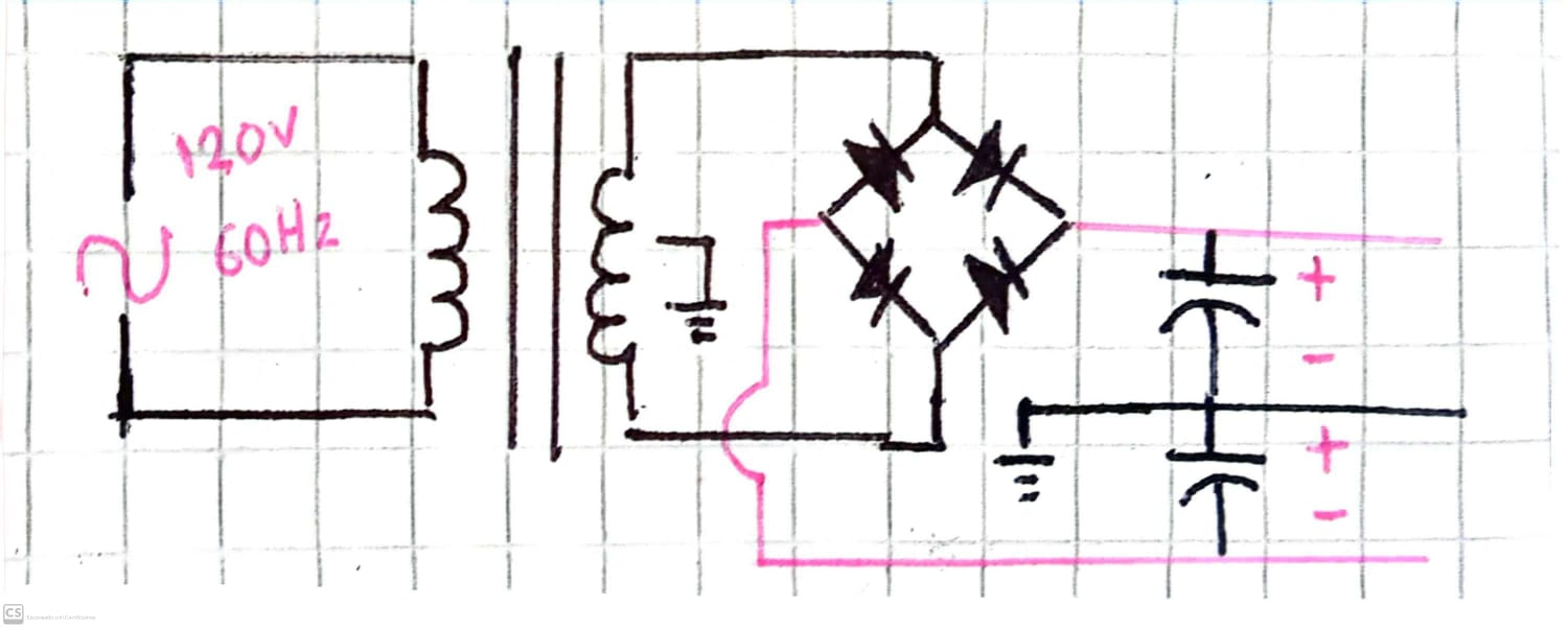
Here is a simple schematic to show where to connect the capacitor. The capacitors shown in the diagram are basic electrolytic capacitors; the polypropylene capacitor is not included because I'm not sure where to place it. Below is a basic circuit for the LM317T and LM337T regulators. enter image description here

\$\endgroup\$
5
  • 1
    \$\begingroup\$ What you have heard might be true, but you don't have any switching componets and thus the capacitor you show is irrelevant where you have drawn it. Basically you have put a capacitor intended for the mains side to the low voltage side, and for the low voltage there are far better options than the capacitor you show, if you need it. But without any need shown, you don't need them. What you usually need is just some bulk electrolytics. If you drew more circuitry that connects to the parts you show, there might be a reason or not. \$\endgroup\$
    – Justme
    Commented Sep 4 at 18:05
  • \$\begingroup\$ the capacitors shown in the schematic are 4700uF electrolytic capacitors, the Polypropylene Capacitors is not added. Far away from the schematic is a basic circuit of a LM317T and LM337T regultador. Sorry if it seems a bit confusing on the little draw i made \$\endgroup\$
    – Zlmanuel87
    Commented Sep 4 at 18:16
  • \$\begingroup\$ What noise are you filtering? \$\endgroup\$ Commented Sep 4 at 18:20
  • \$\begingroup\$ My goal is to reduce the noise from the household electrical supply to provide better quality power for a microphone preamp I am designing. In some places, I have seen that these capacitors are connected before the transformer, but I'm not sure if this is the correct approach. \$\endgroup\$
    – Zlmanuel87
    Commented Sep 4 at 18:26
  • 1
    \$\begingroup\$ @Zlmanuel87 Generally, the trasfomer would not pass household electrical mains supply noise through. If it does, it is the least of your worries as you have an unknown mains inlet connection. Instead of only a capacitor, you could design, or rather buy, a mains filter module. Frankly, putting that kind of capacitor to anywhere in the circuit you have drawn so far has little to no effect to performance of your mic preamp. If it does have a significant improvement, it's the preamp itself you need to improve, not the supply. \$\endgroup\$
    – Justme
    Commented Sep 4 at 18:35

1 Answer 1

1
\$\begingroup\$

I've heard that safety polypropylene capacitors are recommended for filtering high-frequency noise from switching components

It's rather hard to have an argument with hearsay.

The capacitor you have is rated to be connected across the line voltage of up to 240VAC. So it'd be connected directly across the primary terminals of the transformer.

The diagram of the secondary you have shown will not work. The best you can get is one supply (positive or negative):
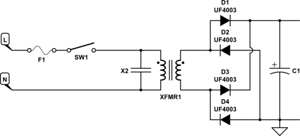
schematic

simulate this circuit – Schematic created using CircuitLab

Quite a bit of switching noise comes from the rectifier diodes on the secondary side of the transformer. You need to use fast types - e.g. UF4001..4007 to minimize that. The "standard" 1N400x rectifiers perform much worse, since they take much more charge to turn off compared to the ultrafast UF400x. That means that after the secondary voltage has fallen below the capacitor voltage, the rectifier conducts too long and discharges the capacitor back into the transformer for a little bit. This builds up the secondary current. Eventually the rectifier turns off and the transformer secondary generates a voltage spike as the current collapses. That's not good, and it's oft overlooked in audio designs. The ultrafast rectifiers will turns off much quicker, and the residual turn-off current in the secondary will be much smaller.

To get symmetric supplies you need a half-bridge rectifier with a single secondary:
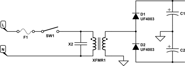
schematic

simulate this circuit

Or you need a full bridge with a tapped secondary:
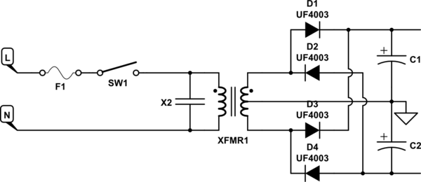
schematic

simulate this circuit

You also should have a power switch and a fuse on the primary side of the transformer. Never skip those two.
\$\endgroup\$
6
  • 1
    \$\begingroup\$ But isn't that a center tapped transformer in the OP's drawing? Sure it might be poorly drawn, but still. \$\endgroup\$
    – Justme
    Commented Sep 4 at 19:25
  • \$\begingroup\$ Thank you so much, it’s exactly what I needed! 👍 \$\endgroup\$
    – Zlmanuel87
    Commented Sep 4 at 19:25
  • \$\begingroup\$ @Justme It was so poorly drawn that I have not even noticed the "center" tap. Seriously. It's late for me I guess :) \$\endgroup\$ Commented Sep 4 at 19:26
  • \$\begingroup\$ @Zlmanuel87 Not really. That is the correct place for the X capacitor, but it does not do much alone to filter much, or is otherwise necessary as the mains transformer usually does not pass high frequencies well due to inductance. \$\endgroup\$
    – Justme
    Commented Sep 4 at 19:28
  • \$\begingroup\$ For 50-60 Hz noise, what recommendations would you give, or is there no problem with that?" \$\endgroup\$
    – Zlmanuel87
    Commented Sep 4 at 19:34

Your Answer

By clicking “Post Your Answer”, you agree to our terms of service and acknowledge you have read our privacy policy.

Not the answer you're looking for? Browse other questions tagged or ask your own question.