ground
For nodal analysis, pick a reference node and call it ground or \$0\:\text{V}\$. This way, the remaining node voltages have an implied reference point. (All voltages are really voltage-differences.)
But keep in mind you can move that reference to any node that is convenient. Don't always accept the given reference, if a different reference point would make things simpler to solve by reducing the number of equations.
That said, the reference you have is fine.
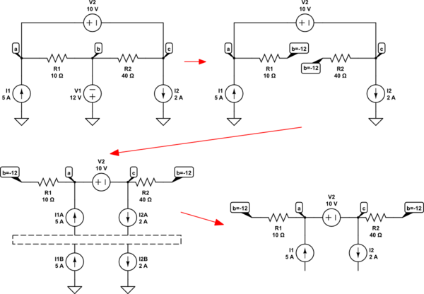
re-draw the schematic
Next, get in the practice of re-drawing schematics. Even if doing so means you have a schematic that the teacher will not accept as a valid answer. The skills you develop in re-drawing schematics will serve you well.
The process isn't formulaic and there isn't only one way to go with it. This is another reason to practice a lot. Doing so develops your own unique style that communicates to your mind better and, because of that, may allow you to communicate ideas to others more readily, as well.
Let's take your schematic and look at one possible result:

simulate this circuit – Schematic created using CircuitLab
Current sources can be broken into two parts, as shown in the 3rd rendition above. And there's no need to analyze the ground node. So that entire lower section in the 3rd rendition can be chucked out the window, as shown in the 4th rendition above.
super-node
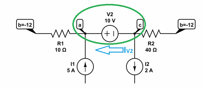
Now, this does have a super-node, as shown in the green oval below:

The only reason for a supernode here would be if you don't care about knowing \$I_{V_2}\$ and just want to develop a single KCL statement for the entire supernode -- using either one of \$V_a\$ or else \$V_c\$ as the reference. This would be a good way to go if solving this without a computer and just using paper and pen, instead. (You could then later work out the current from that result.)
$$\begin{align*}
\underbrace{\frac{V_c+V_2}{R_1}+\frac{V_c}{R_2}+I_2}\quad&=\quad\underbrace{\frac{V_b}{R_1}+\frac{V_b}{R_2}+I_1}\\
\text{leaving super-node}\quad&\quad\:\:\text{entering super-node}
\end{align*}$$
This solves out as \$V_c=V_b-V_2\cdot\frac{R_2}{R_1+R_2}-\left(I_2-I_1\right)\cdot\left(R_1\vert\vert R_2\right)\$. Which does work out to \$V_c=+4\:\text{V}\$. And from there you can get the rest. (\$V_b=-12\:\text{V}\$.)
without using a super-node
On the other hand, if you want to include the current through \$V_2\$ then a supernode isn't required and you can instead just assign a new variable, \$I_{V_2}\$, to the current (pick a direction, of course) in \$V_2\$. Here, you then leave both \$V_a\$ and \$V_c\$ as unknowns and add a third unknown, \$I_{V_2}\$. This will mean solving for three equations and three unknowns, but you will know in advance that \$V_a=V_c+V_2\$ so this gives you one of the equations needed. The KCL rule will let you develop the other two equations.
$$\begin{align*}
\frac{V_a}{R_1}&=\frac{V_b}{R_1}+I_1+I_{V_2}\\\\
\frac{V_c}{R_2}+I_2+I_{V_2}&=\frac{V_b}{R_2}\\\\
V_a&=V_c+V_2
\end{align*}$$
That solves out to \$V_a=+14\:\text{V}\$, \$V_c=+4\:\text{V}\$, and \$I_{V_2}=-2.4\:\text{A}\$ (meaning I got the current arrow direction wrong.) But it required three equations and three unknowns. (\$V_b=-12\:\text{V}\$.)
modified nodal analysis
This isn't either of the above, exactly. And I believe this page is pretty nice for discussing MNA. MNA is really more targeted at computerized (rote algorithmic development) analysis, though it works just fine by hand.
That page shows you how the unknowns are laid out into matrix form for developing solutions. MNA would definitely consider \$I_{V_2}\$ to be an unknown to solve and, because it takes a rote algorithmic approach that is easy to code as software and solves all of the unknowns, isn't interested in the use of super-nodes.


supernodeis part and parcel with the idea of the "node voltage method" (nodal analysis), and explicitly is not part ofmodified nodal analysis. MNA obviates the need for the supernode concept. \$\endgroup\$