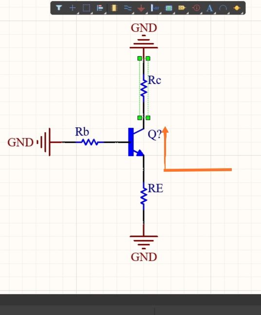
You need to write a lot more. For example, what is \$R_m\$? Is it \$r_e^{\:'}\$? (I'm randomly guessing.) What does when it's open mean in the case of looking into the emitter, which implies a common base configuration to me.
I will choose to emphasize the looking into the emitter part and assume this is a common base arrangement. Perhaps the sum \$r_o\$ and \$R_{_\text{C}}\$ part of your question may arrive a little better for me when you write more. (I can kind of see, but if so I'm not sure why you are asking and it doesn't fly well with me.)
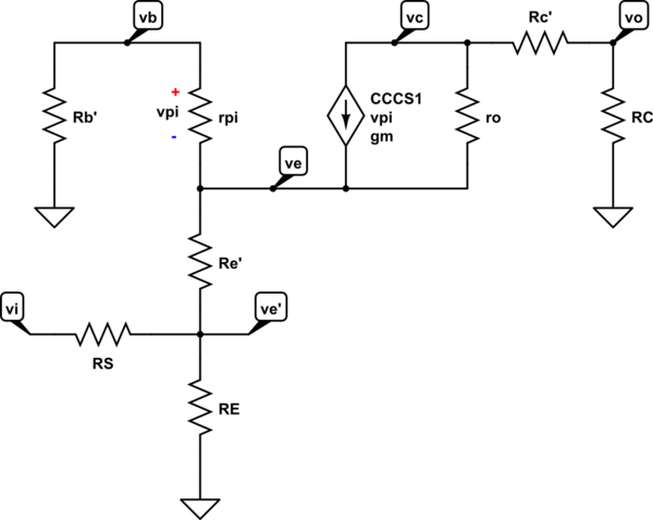
Avoiding capacitances, the small signal model looks something like this for common base:

simulate this circuit – Schematic created using CircuitLab
The above assumes that the base is effectively AC-grounded, likely using a capacitor.
It includes the source impedance, \$R_{_\text{S}}\$. In your case, I would tend to assume you don't care about it and would set \$R_{_\text{S}}=0\:\Omega\$. But I'm keeping it to be more complete.
It also includes the bulk impedances for all three terminals, \$R_{\text{b}}^{\:'}\$, \$R_{\text{c}}^{\:'}\$, and \$R_{\text{e}}^{\:'}\$. You may want to just set \$R_{\text{b}}^{\:'}=0\:\Omega\$, \$R_{\text{c}}^{\:'}=0\:\Omega\$, and \$R_{\text{e}}^{\:'}=0\:\Omega\$. But it actually appears to me that your question implies \$R_{\text{b}}^{\:'}\ne0\:\Omega\$. So maybe you just aren't considering the other two?
It also includes the external collector and emitter resistances, \$R_{_\text{C}}\$ and \$R_{_\text{E}}\$. \$R_{_\text{C}}\$ is certainly important to know. But depending on what you care about (see following) it may be that \$R_{_\text{E}}\$ isn't important.
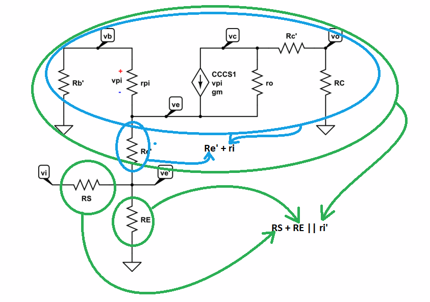
In the above case the impedance looking into the emitter will be \$R_{_\text{S}}+R_{_\text{E}}\vert\vert \:r_i^{\:'}\$, where \$r_i^{\:'}\$ may be closer to what you want to know about.
This diagram may help to see where we are at this point:

\$r_i^{\:'}\$ will, of course, be \$R_{\text{e}}^{\:'}+r_i\$, where \$r_i\$ may be the actual value you are looking for.
If you want to exclude the bulk impedances, except for \$R_{\text{b}}^{\:'}=0\:\Omega\$, exclude \$R_{_\text{E}}\$, and set \$R_{_\text{S}}=0\:\Omega\$ then you will need to know \$R_{\text{b}}^{\:'}\$, \$r_\pi\$, \$r_o\$, \$g_m\$ and \$R_{_\text{C}}\$.
But as I said, I don't understand your writing well.
In any case, if you don't include the bulk collector and emitter impedances then: \$r_i=\frac{\left(R_{_\text{C}}+r_o\right)\,\cdot\,\left(R_{\text{b}}^{\:'}+r_\pi\right)}{R_{_\text{C}}+r_o+R_{\text{b}}^{\:'}+r_\pi\,\cdot\,\left(1+g_m\,\cdot\, r_o\right)}\$. If you do include them, but discount \$R_{_\text{S}}\$ and \$R_{_\text{E}}\$, then it is a little more complex: \$r_i^{\:'}=R_{\text{e}}^{\:'}+\frac{\left(R_{_\text{C}}+r_o+R_{\text{c}}^{\:'}\right)\,\cdot\,\left(R_{\text{b}}^{\:'}+r_\pi\right)}{R_{_\text{C}}+r_o+R_{\text{c}}^{\:'}+R_{\text{b}}^{\:'}+r_\pi\,\cdot\,\left(1+g_m\,\cdot\, r_o\right)}\$.
If you lift the grounded base, so that \$R_{\text{b}}^{\:'}\$ is floating, then the above fails. More so because \$v_\pi=0\$ and \$r_o\$ no longer applies since it models a basewidth effect that doesn't apply in the same way as before. In addition, without the AC grounding (capacitor?) at the base, you now have a DC biasing impedance to ground seen from the base, in addition. This is probably what really flummoxes me more about your question, as the DC base biasing impedance becomes dominant here.
Note: I'll stop at this point, because I really don't understand well the problem you are setting out. You need to write better and more. I will extend the answer (or remove it) when you clarify where you are headed. The intent up to this point is to get you to clarify your question.


