1
\$\begingroup\$

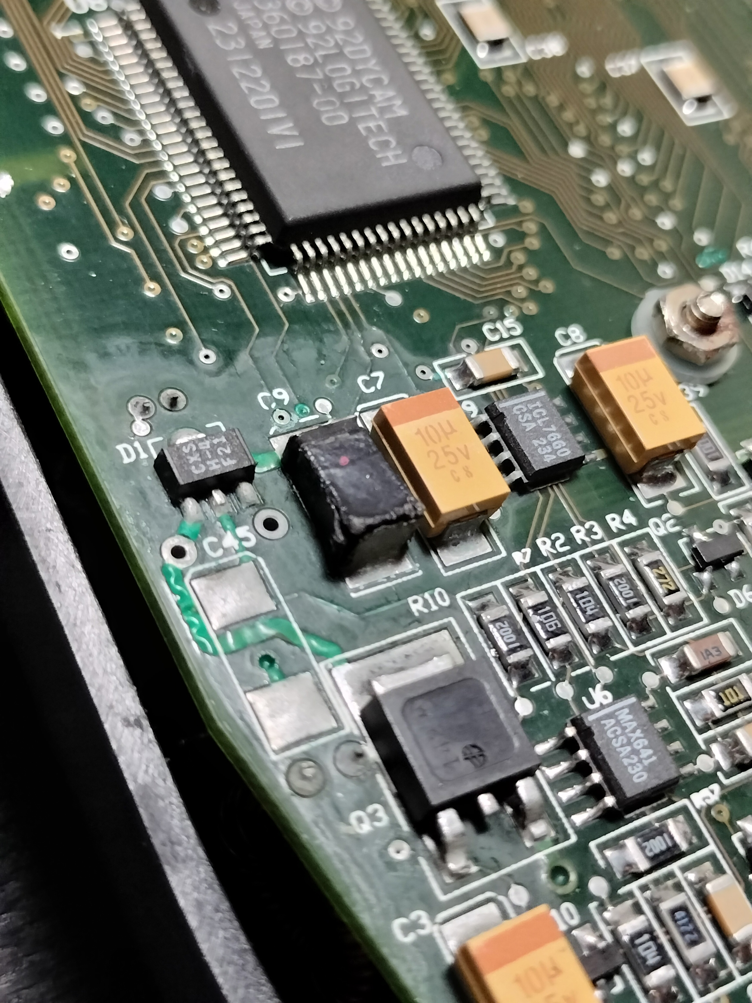
I have a device that has a blown up component, and I would like to try and replace it (as well as repairing damaged traces and cleaning up some corrosion) to see if the device still functions.

This is a digital camera released in 1992 (A Dycam Model 3), and I have searched far and wide for a schematic, but have had no luck finding even a hint.

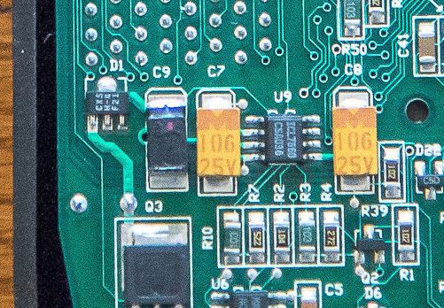
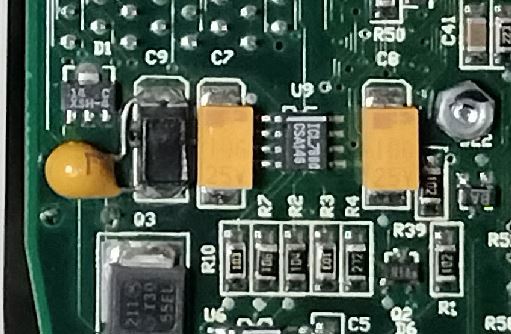
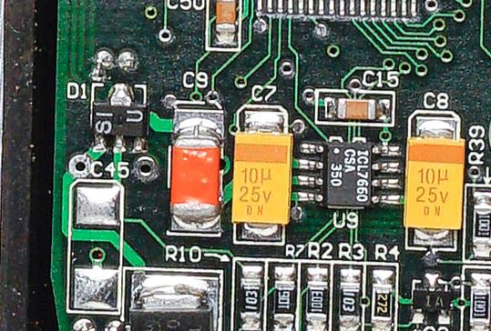
I have found 3 images of similar devices (some from a year or two earlier, some from a year or so later), and they all seem to have the same setup surrounding this failed component.

The ICL7760 chip between the 2 tantalum caps is a voltage converter IC, and the larger SMT Q3 is a MOSFET transistor. I am fairly certain this complex is part of the power supply, or maybe the charging circuit. The device runs on 2x 1.2V NiCd batteries that are recharged in the device itself.

Searching any combination of the numbers and letters visible on the SOT-89 component directly to the left of the blown up device brings up no useful results. I have also searched for the alternative chip seen in one of the images, labeled "SI U", also with no results. I believe based on the "D1" silkscreen, that this SOT-89 chip is a diode of some kind.

The component C9 seems to have an alternate form in the same photo with the alternate SOT-89 chip, as well. The black cubic components on my device and the others in the photos seem to either have small red dots or grooves on their solder pads to indicate polarity. The black cubic package reminds me of a diode, but it is labeled C9 indicating it might be a capacitor. The orange package in the alternative style definitely reminds me of a capacitor. One of the found photos also seems to have a through-hole tantalum capacitor across the pads for the C9 device, which to me makes it look like the C9 device itself is not a capacitor.

I would like to try and identify the D1 chip to help understand what the C9 device is. I am not a whiz with electronics, but have the troubleshooting skills and tools necessary to measure continuity and resistance, but I need some help in understanding what I could measure that would be helpful for identifying these 2 devices.

I am away from my desk right now, but I will measure continuity to determine where the bottom pad of C9 connects to, I suspect one of the left-side pins on the U9 voltage converter IC based on the last image here.

EDIT: I have inspected the datasheet for the ICL7660 IC datasheet, and there are plenty of example circuits shown, but none seem to show what is going on here, at least to my untrained eyes.

Thank you for the guidance!

Close-up view of a portion of a PCB with a square black component that is deformed and visibly burnt

Found photo of a similar undamaged device from an overhead view

Found photo of a similar undamaged device from an overhead view

Found photo of a similar undamaged device with alternate components from an overhead view

\$\endgroup\$
4
  • \$\begingroup\$ Sorry, I forgot to add that to the post. I have inspected the ICL7760 datasheet, and there are lots of example circuits, but none seem to match what seems to be going on here. It does tell me, though, that those 2 10u tantalum caps are part of the 7760 circuit. \$\endgroup\$ Commented Sep 24 at 15:09
  • 1
    \$\begingroup\$ Your pictures are confusing, the boards are routed slightly differently. It can't very well be a series capacitor since this looks neither like AC nor RF electronics. Assuming it is is a bulk decoupling cap, not unlikely around the same 10uF flavour as the rest. Now if you desolder the charcoal remains, you'll probably find a ground via underneath it and which pad it goes to will matter, as this looks like 2 layer design where C9 is a bulk cap belonging either to the Q3 part or the U9 part. \$\endgroup\$
    – Lundin
    Commented Sep 24 at 15:25
  • \$\begingroup\$ ICL7660*, right? \$\endgroup\$ Commented Sep 24 at 15:45
  • \$\begingroup\$ I just believe C9 is a tantalum capacitor. Sometimes one do a repair by adding a good capa to the bad one, without removing it. Desolder C9 and try to analyse it (cut it in half with a small grinder). Maybe its capacity is not totaly gone, try to measure it anyway. \$\endgroup\$
    – user317139
    Commented Sep 24 at 15:46

3 Answers 3

1
\$\begingroup\$

You'll have to do more reverse-engineering to figure out C9, I think. Remove some components to see traces underneath them, ohm out connections to see where they go.

C9 being a burned tantalum, is entirely possible, consistent with their behavior. Namely that they tend to ignite when connected to low-impedance supply rails, especially when sudden (inrush). (They really do ignite: their construction is a porous Ta pellet impregnated with MnO2, a moderate oxidizer; given enough heat, Ta and Mn exchange oxygen, liberating Mn metal, and a lot of heat -- a thermite reaction.)

D1 can be found directly, at least the one version: Central CXSH-4 is a standard part.* Curiously, pin 3 isn't connected (or, it doesn't seem to be here), but given the internal connection, that probably doesn't matter.

*Was? Never can quite be sure with Central, heh. They make a lot of legacy products. I don't see any in stock at least (one major distributor (Arrow) does have a catalog entry).

The choice of SOT-89 (TO-243) is very peculiar indeed. I've never seen such a diode in a product myself (not that I've taken apart a lot of things, mind), and there's less than a dozen listed on Digikey (including two "array" types returned in a separate search). Doesn't mean they weren't used more in previous years or something, but it certainly sounds uncommon, which likely helps narrow down the possibilities. Of those listed, most have a "Sx" marking scheme -- though neither seem to use 'I' or '1' as shown here. Perhaps the lettering is sequential, though without a series listing, it's impossible to say where these products fall.

It would be safe to assume it's a diode, probably a schottky diode, probably in the 30V 1A ballpark. If you have a known-good part, you can test it for characteristics (particularly Vf (say at 1mA, 1A, etc.), Vbr (say at 1mA) and Cjo) and see what's comparable.

It's possible Q3 is a switch, enabling the local section, which might in turn be a voltage doubler or inverter (perhaps to run some analog or CCD function elsewhere). Not clear what the part number is, but I think there's a Motorola (now onsemi) logo on the DPAK, and perhaps "3055EL", which would be MTD3055EL. If this node is a positive supply, it doesn't make any sense coming off the drain of an N-MOS, but again, lacking context here, anything is possible. If this is a switched local supply, and the transistor is driven too hard, it could well be argued this is a design fault, causing the tantalum to eventually, sometimes, ignite. There also seems to be a capacitor underneath, THT in some (older?) versions, C45 in others.

\$\endgroup\$
1
\$\begingroup\$

D1 could be a CXSH-4 Schottky Diode by Central Semiconductor which fits the D-designator. Besides, there are several reasons to have a Schottky diode in front of a voltage regulator, so that's a quite plausible guess.

From the datasheets of ICL7660 and CXSH-4 it appears that we are dealing with voltages below 20V.

C9 suggests that the damaged component is a capacitor (those typically "fail short").

I recommend a trial and error approach:

  1. Desolder the broken capacitor and see what the device does. In case the capacitor just provides bulk or decoupling capacity there's a chance that already does the trick. Not all capacitors are mandatory from a hobby perspective and a missing cap is still better than a short.

  2. Replace C9 with a capacitor between 1uF and 10uF and a voltage rating >20V. If it still doesn't work...

  3. There's a chance that other components are also damaged but to find those, you'll have to reverse-engineer the circuit.

\$\endgroup\$
2
  • \$\begingroup\$ I would guess based on the silkscreening on D1 that the CXSH-4 is the right component. I swear I googled that multiple times and got nothing. I just googled "CXSH-4 SOT-89" now and got immediate hits. I am thinking, based on my previous mis-typing of the IC chip in a comment, I just typed it dyslexic-ly. \$\endgroup\$ Commented Sep 24 at 17:05
  • \$\begingroup\$ @KyleGagnon it often helps to add "datasheet" ;) \$\endgroup\$
    – Sim Son
    Commented Sep 24 at 17:13
0
\$\begingroup\$

The D1 component appears to be a voltage regulator from Seiko Instruments ; S-817B55AMC-CXST2G or the S-817B55AUA-CXST2G, however it may also be manufactured by others such as Ablic. All other hits do not match to the same footprint ...

\$\endgroup\$

Your Answer

By clicking “Post Your Answer”, you agree to our terms of service and acknowledge you have read our privacy policy.

Not the answer you're looking for? Browse other questions tagged or ask your own question.