3
\$\begingroup\$

This circuit is supposed to work as a logic gate. I need to find out the logic operation it performs. Suppose the diodes are ideal.

https://www.circuitlab.com/circuit/egg3wh/logicgate/
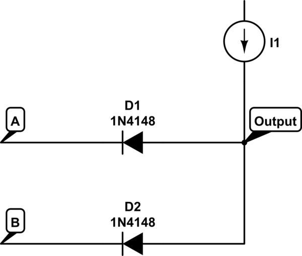
schematic

simulate this circuit – Schematic created using CircuitLab

Now when the circuit is implemented with voltage sources, I know the general approach to solve this. You check the voltage at the anode and cathode of the diodes and determine whether or not it is conducting....

With a current source I am kind of confused on what to do. I can't determine the state of the diodes for a given input combination (00, 01, 10, 11) because I don't know the voltage at the anode of the diodes.

I think the problem is that I am not used to current source driven diodes.

Can anyone provide some guidance?

Thank you.

\$\endgroup\$
5
  • \$\begingroup\$ I have simulated the circuit using LTSpice and it seems like the output is high when both A and B is high. If both A and B are low or if one of A and B is low, the output is low. Why? How do you solve this kind of circuit? How is a current source usually dealt with in this case? \$\endgroup\$ Commented Jun 15, 2013 at 14:04
  • \$\begingroup\$ You have concluded it is a NAND gate and I agree. Do you understand the forward conduction characteristics of a diode? This will help you, and if you are uncertain by the current source just imagine it is a high value resistor connected to (say) +5V \$\endgroup\$
    – Andy aka
    Commented Jun 15, 2013 at 14:26
  • \$\begingroup\$ @Andy: NAND?? \$\endgroup\$ Commented Jun 15, 2013 at 15:18
  • \$\begingroup\$ I have managed to figure out 00, 01, 10. If any one of the input is low and the output is high, diode will be forward biased and act as a short, and there will be a contradiction of voltage levels. Therefore the output has to be low if any of the input is low. Now for the 11 case I don't see how to reason since both cases (output 1 and 0) seem possible... \$\endgroup\$ Commented Jun 15, 2013 at 15:40
  • \$\begingroup\$ Maybe a thought experiment helps? If you consider a single diode, in series with a very low resistor, say 0\$\Omega\$ what is the output voltage in that case? Then slowly increase that resistor 1\$\Omega\$, 10\$\Omega\$, ... what happens to the output in that case? What happens if you increase the resistor even further (to \$\infty\$)? \$\endgroup\$
    – jippie
    Commented Jun 15, 2013 at 16:03

2 Answers 2

1
\$\begingroup\$

There are 2 ways to understand this.

  1. Replace Current Source with a "Voltage source with a resistor in series (+ve where current goes out)". Now you can imagine that there will be output only if both diodes are blocked, otherwise all current will be grounded.
  2. A current is originating from source and it needs a path to ground. It always selects a low resistance path. If N terminal of diode is grounded (logic 0 attached), it is forward bias (ideally there is no +0.7V required). Current takes 0 resistance path irrespective of load and hence 0 output. If any voltage is attached at N terminal (logic 1), it will be reverse bias and so open circuit, current will go to output.

Other than that, practically speaking, HIGH logic state in practice never behaves as ground (0), although at times it may behave as 1.

\$\endgroup\$
0
\$\begingroup\$

I can understand your confusion. It all comes down to how you define the logic levels.

If either of the diodes is connected to a low input it will pull current through it.

Normally this circuit pulls a VOLTAGE low and it is the voltage that is used to define the output.

By using a current source, current will only flow if either or both diodes are grounded.

If we define the presence of current as '1' and its absence '0'

then the grounding of a diode = current = '1'

                      A        B          Out

                      0        0           0
                      0        1           1
                      1        0           1
                      1        1           1

it forms an OR GATE

If we define '1' as a voltage HIGH, and '0' as a voltage LOW we get, the output will be HIGH with both inputs not connected. (Both inputs HIGH)

                      A        B           Out
                      0        0            0
                      0        1            0
                      1        0            0
                      1        1            1

it forms an AND GATE

If we mix definitions - Inputs as high/low voltages Output as a current we get

                      A        B            Out 
                      0        0             1
                      0        1             1
                      1        0             1
                      1        1             0

it forms a NAND gate

So just like you I am confused because what constitutes a logic state (current, voltage or a mixture) is not defined.

As using LTSpice seems to like the "both high in gives a high out" it must define the logic in terms of the voltages (the middle option in this answer) so it will be an AND gate.

\$\endgroup\$
3
  • \$\begingroup\$ In other words, it could be a "flexible" gate of sorts... XD \$\endgroup\$ Commented Jun 16, 2013 at 6:15
  • 1
    \$\begingroup\$ @haneefmubarak Not really 'flexible' - this is an AND gate by the common definition of high and low referring to voltage rather than current. \$\endgroup\$ Commented Jun 16, 2013 at 9:25
  • \$\begingroup\$ By flexible, I meant that depending on what you constitute a signal, you could get different gates. IF you made a signal converter of sorts, you could have a variety of connected gates. (PS: Look at the "XD" sideways). \$\endgroup\$ Commented Jun 16, 2013 at 18:54

Not the answer you're looking for? Browse other questions tagged or ask your own question.